


Corrective Maintenance
Maintenance
6Ć26
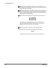
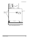
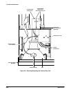
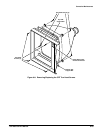
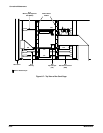
See Figures 6Ć23, 6Ć26, and 6Ć32 for connector, screw, and index locations.
Remove and replace the Acquisition unit as follows (the Acquisition unit can
be removed with the instrument in the normal upright position for all steps):
CAUTION
Lifting the trim covers to remove them will break the trim covers.
There is a clip on the inside of the trim cover that slides over the
end of the side frame section. To remove the trim covers, move
each cover toward the end of the instrument where it is located.
(The front cover moves forward and the rear cover moves backĆ
ward.) Moving the clip about 1/8Ćinch will release the cover. Then,
the cover can be removed from the instrument.
ăStep 1:ăRemove the bolt from the top of the chassis, just behind the
front casting.
ăStep 2:ăRemove the trim covers from the right side (as viewed from the
front of the instrument).
ăStep 3:ăRemove the two Torx head screws holding the frame section
and remove the frame section.
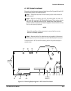
ăStep 4:ăRemove connectors J10 on the A26 M/F Acquisition InterconĆ
nect board and J34 on the A19 Strobe/TDR Buffer board. Note the
position of the connectors' index triangles to ensure that the multiĆpin
connectors can be correctly replaced.
ăStep 5:ăRemove connectors J29A, J30A, J32, J33A, and J33B on the
A19 Strobe/TDR Buffer board.
ăStep 6:ăGrab between the two sampling head slots and gently pull out
the Acquisition unit a few inches.
ăStep 7:ăRemove the gray ground wire from the rear of the Acquisition
unit.
ăStep 8:ăRemove the Acquisition unit.
CAUTION
To prevent damage to interconnecting wires, be careful not to pinch
any interconnecting wires when replacing this unit.
To replace the Acquisition unit, perform the previous steps in reverse order.
Acquisition Unit
Removal/
Replacement