


Diagnostic Troubleshooting
Maintenance
6Ć98
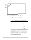
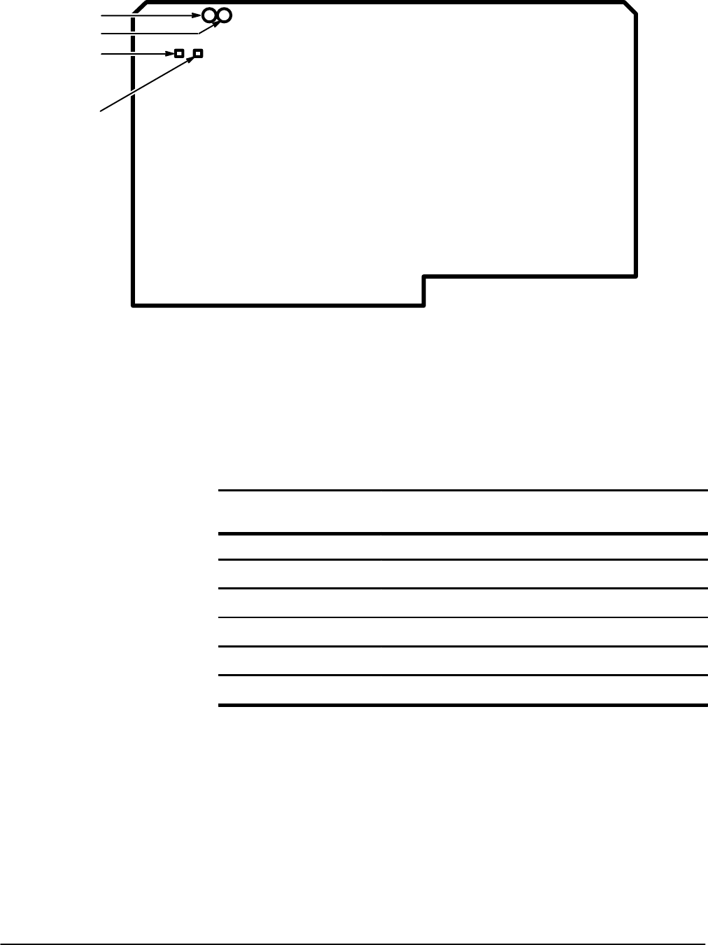
DS200
DS201
DIAG 0
(LSB)
DIAG 2
(MSB)
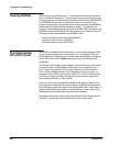
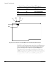
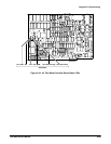
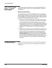
Figure 6Ć34:ăA15 MMU Board Test Point and Status LED Locations
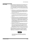
Time Base Processor Error Index Codes
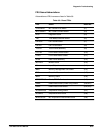
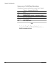
Error index codes for the Time Base processor are listed in Table 6Ć15.
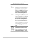
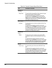
TableĂ6Ć15:ăTime Base Processor Kernel Error Index Codes
Error Index
hex
Suspect Hybrid/
IC FRUs
Suspect Board FRUs
1 TBC
2-3 FW TBC
4-7 TBC
8-A TBC, MMU
B TBC
C TBC, MMU
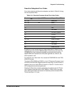
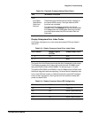
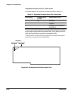
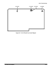
The error index code bits of the first Time Base kernel test that fails are read
from the A5 Time Base/Controller board status LEDs ST4 (MSB), ST3, ST2
and ST1 (LSB). The bits are true (one) when the LED is on. Also, status
LEDs ST5 and ST6 indicate when the test is executing and when the test
has failed, respectively. See Figure 6Ć35 for the location of these status
LEDs.
The patterns from the status LEDs are applicable only when the Time Base
is executing or stopped in Kernel diagnostics.