


Other Troubleshooting
CSA 803C Service Manual
6Ć103
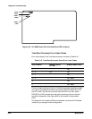
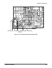
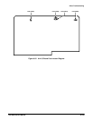
The A14 I/O board has four fuses (see Figure 6Ć37). F200 supplies +5 V to
the A12 Rear Panel board. F800 supplies +5 V to the A10 Front Panel ConĆ
trol board and the A9 Touch Panel board. F600 supplies +15 V to the
A14 I/O board, card cage, A10 Front Panel Control board, A9 Touch Panel
board, A11 Front Panel Button board, and A12 Rear Panel board (reduced
to +12 V). F602 supplies -15 V to the A14 I/O board, card cage, A10 Front
Panel Control board (reduced to -5 V), and A12 Rear Panel board (reduced
to -12 V).
H F200 supplies +5 V to the A12 Rear Panel board. If diagnostics report
failure of all three ports (RSĆ232ĆC, GPIB, and PRINTER), then this fuse
is the probable suspect (assuming that the ribbon cable to the A12 Rear
Panel board is connected). When tested with a multimeter, this fuse
should measure less than 1.5 V.
H F800 supplies +5 V to the A10 Front Panel Control board and the
A11 Front Panel board. If the diagnostics report both an A9 Touch Panel
board failure and knob failures, then this fuse is one possible source of
this problem. When tested with a multimeter, this fuse should measure
less than 1 W.
H F600 supplies +15 V to the A14 I/O board temperature sensor and tone
generator, the lights of the A11 Front Panel Button board, the A9 Touch
Panel board, the A12 Rear Panel board's RSĆ232ĆC output line drivers,
the card cage, and the A17 Executive Processor board's NVRAM. If the
NVRAM battery test and the RSĆ232ĆC External Loop Back test fail (but
the Internal Loop Back test passes), and the A11 Front Panel Button
board's lights, temperature sensor, and tone generator are all off, then
this fuse is the probable suspect. When tested with an multimeter, this
fuse should measure less than 1 W.
H F602 supplies -15 V to the A14 I/O board temperature sensor and tone
generator, A12 Rear Panel board's RSĆ232ĆC output line drivers, the
A9 Touch Panel board, and the card cage. If the temperature sensor,
tone generator, and RSĆ232ĆC External Loop Back test fail (but the
Internal Loop Back test passes), then this fuse is the probable suspect.
When tested with an multimeter, this fuse should measure less than 1 W.
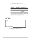
The A14 I/O board uses the +15 V and -15 V supplies on board to operate
the temperature sensor and the tone generator. Of the other card cage
boards, the A18 Memory board uses the +15 V supply to operate the
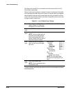
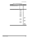
NVRAM circuitry. The information above and Table 6Ć17 will help you to
identify a failure of one of these fuses. If a test fails, then check the fuses.
WARNING
Using a replacement fuse with an incorrect current rating may
cause the ribbon cables to melt and create fire danger during a
component fault.
Fuse Testing