


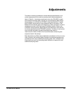
Adjustments
CSA 803C Service Manual
5Ć7
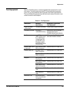
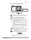
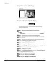
This procedure shows the setup and lists the steps to examine the MeaĆ
sured Voltage Supply and to check and adjust the Voltage Reference and
the Regulator Reference (see Figures 5Ć1, 5Ć2, and 5Ć3).
This procedure should only be performed if the instrument is out of
measurement limits and maintenance is required. If the CSA 803C is
already within limits, proceed to the Display adjustment procedure.
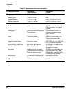
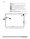
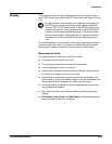
Measurement Limits
The measurement limits for this procedure are as follows:
H Measured Voltage Supply limits must be within +4.85 V and +5.25 V
H Voltage Reference must be within +5.15 V and +5.25 V
H Regulator Reference must be within +9.95 V and +10.05 V
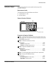
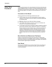
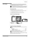
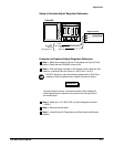
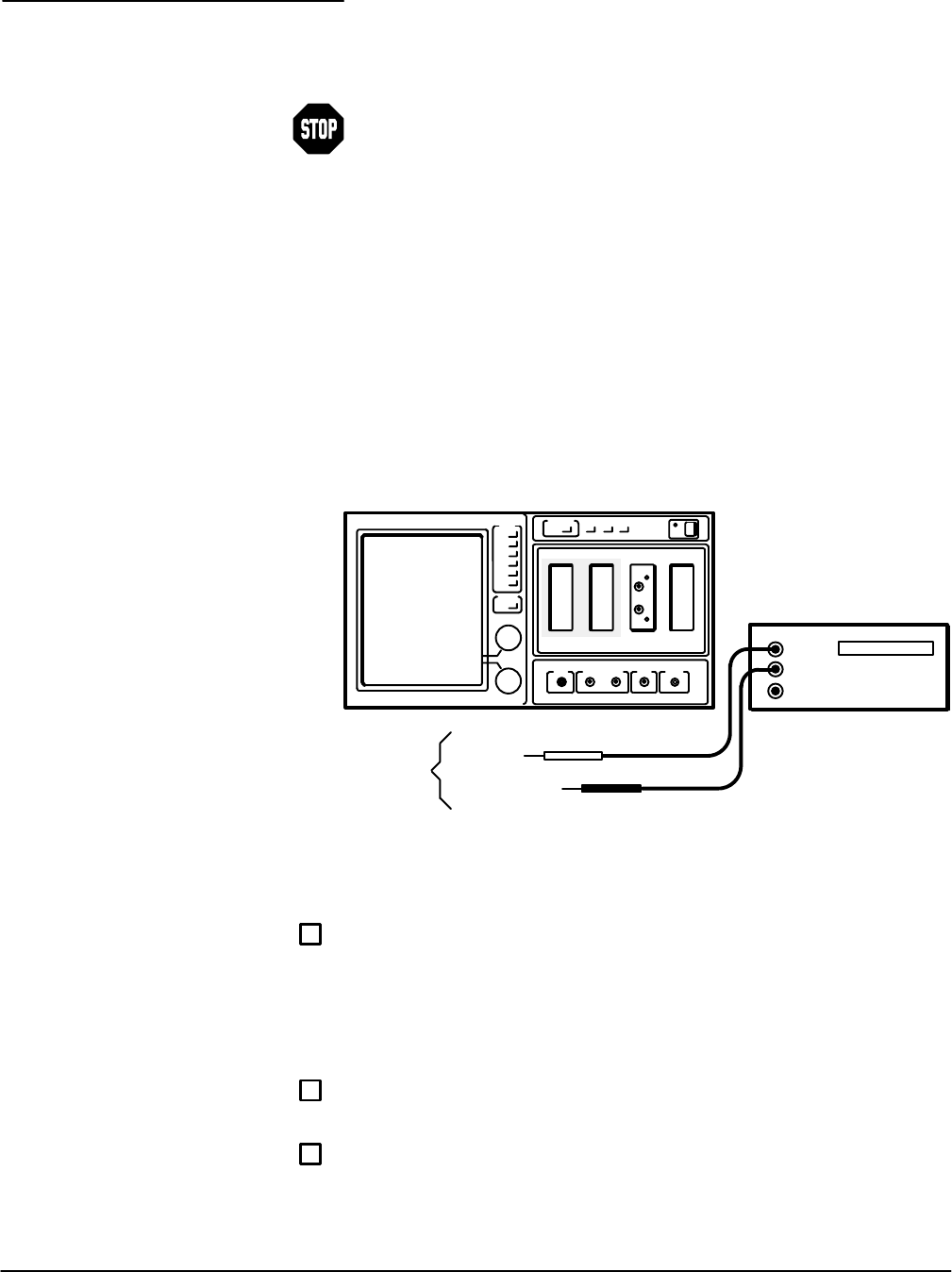
Setup to Examine Voltage Supply
CSA 803C
TP200 (VCC) and
TP300 (GND) on A18
Memory Board
(see Figure 5Ć1)
To Ground
To +5 V
Digital Voltmeter
Hi
Low
Procedure to Examine Voltage Supply
ăStep 1:ăSet the CSA 803C ON/STANDBY switch to ON, and initialize as
follows:
UTILITY button press...........................................
Initialize (in major menu) touch..............................
Initialize (in verification popĆup menu) touch..................
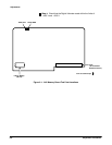
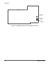
ăStep 2:ăWith the CSA 803C top and bottom covers removed, refer to
Section 3 and locate the A18 Memory circuit board.
ăStep 3:ăConnect the digital multimeter to TP200 and TP300 as indicated
in the setup illustration (see also Figure 5Ć1).
Power Supply