


Block Diagram Descriptions
Theory of Operation
3Ć14
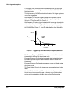
Degauss
This circuit removes magnetic fields from the color steel aperture grille.
These magnetic fields are induced at each powerĆon by magnetic sources.
The Degauss circuit produces an exponentially decaying sine wave with a
frequency of approximately 3.7 kHz. This waveform is applied to the deĆ
gauss coils that are located on both sides of the CRT. The decayed oscillaĆ
tion through the coils causes a magnetic field to be induced in the CRT steel
aperture grille. This magnetic field saturates the steel and then forces the
stored magnetic field down to zero as the steel is driven around its hystereĆ
sis curve.
Beam Current Limit
This circuit limits the average power to the CRT to less than 15 W. An ampliĆ
fier circuit compares the sum of the anode current and the FOCUS adjustĆ
ment current to a reference current of 0.72 mA. If the sum of the two
currents exceeds the reference current, then the three video amplifiers on
the A7 CRT Socket board are disabled.
Grid Bias
This circuit provides -40 V of grid bias to the A7 CRT Socket board. At
powerĆoff, the grid is supplied with -90 V until the focus circuit discharges a
high voltage. This prevents a bright spot from appearing at the center of the
screen at powerĆoff.
The A9, A10, and A11 FrontĆPanel Circuit boards specifically consist of the
following boards:
H A9 Touch Panel assembly
H A10 Front Panel Control board
H A11 Front Panel Button board
Touch Panel, Major Menu Keys, and Menu Status LEDs
These three functions interface to the Executive processor through a general
purpose programmable keyboard and display controller IC on the A10 Front
Panel Controller board.
The keyboard function of the IC handles the touch matrix and hard keys.
The display function drives the menu LED light bars.
A9, A10, and A11
Front Panel Boards