


Corrective Maintenance
CSA 803C Service Manual
6Ć45
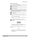
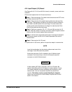
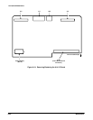
A12 Rear Panel Assembly
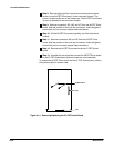
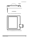
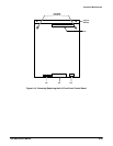
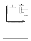
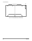
Removal and replacement steps are listed below. See Figures 6Ć2, 6Ć17 and
6Ć32 for connector, screw, and index locations.
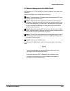
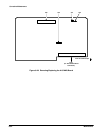
ăStep 1:ăRemove the connectors from the RSĆ232ĆC, the GPIB, and the
PRINTER connector holders.
ăStep 2:ăRemove the eight Torx head screws from the outer edges of the
rear panel connector plate.
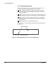
ăStep 3:ăTilt the plate back from the instrument. Remove connector J78
from the top of the A12 Rear Panel assembly. Remove the grounding
wire. Note the position of the connector's index triangle to ensure that
the connector can be correctly replaced.
ăStep 4:ăRemove the rear panel connector plate and the attached A12
Rear Panel Assembly.
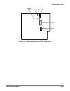
ăStep 5:ăRemove the following items from the rear panel plate:
H two bail brackets, screws, and washers from the PRINTER connecĆ
tor
H two posts from the GPIB connector
H posts, lockwashers, and flat washers from the RSĆ232ĆC connecĆ
tor(s)
H Torx head screw and washer (at lower left, if present)
ăStep 6:ăRemove the A12 Rear Panel Assembly from the rear panel
connector plate.
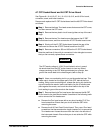
CAUTION
The metal covers on the PRINTER and on the GPIB connectors are
loose. If the board is inverted, these covers will fall off.
To replace the A12 Rear Panel assembly, perform the previous steps in
reverse order.
NOTE
Replacement of connector J78 will be simplified if you replace the
connector before reinstalling the rear panel connector plate on the
rear of the chassis.