


Corrective Maintenance
CSA 803C Service Manual
6Ć47
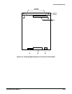
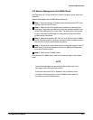
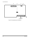
A13 Mother Board
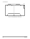
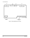
Removal and replacement steps are listed below. See Figures 6Ć7, 6Ć18 and
6Ć32 for connector, screw, and index locations.
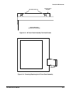
ăStep 1:ăRemove the three Torx head screws that secure the CRT cover,
and then remove the CRT cover. Remove the card cage retainer from
the top front of the card cage by removing the card cage's two screws.
Remove both circuit board guides from the top of the card cage. The
other ends of the guides contain slots that attach to the edge of a metal
bracket. Both ends of the guides can be pried loose.
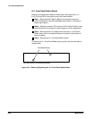
ăStep 2:ăRemove the A14 I/O, A15 MMU, A17 Executive Processor, and
A18 Memory boards. Note the position of the multiĆpin connectors' index
triangles to ensure that the connectors can be correctly replaced.
NOTE
Tag the interconnecting plugs and mark the board locations to
ensure that the plugs can be correctly replaced as well.
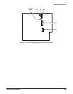
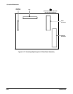
ăStep 3:ăRemove connector J63A from the A13 Mother board.
ăStep 4:ăRemove the six Torx head screws.
ăStep 5:ăRemove the A13 Mother board.
To replace the A13 Mother board, perform the previous steps in reverse
order.
CAUTION
To prevent damage to the interconnecting wires, be careful not to
pinch the wires along the inside edge while replacing this board.