


Block Diagram Descriptions
CSA 803C Service Manual
3Ć11
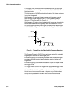
change. Triggering is held off to beyond the rightmost point in the Main
record. The minimum value is 5 ms. The Actual Holdoff (auto mode) calculaĆ
tion is:
Actual Holdoff (auto mode) = max (5 ms, 5 ms+Main Pos+Duration)
where Duration = Main Size 10 divisions.
Manual Holdoff extends the trigger holdoff to longer periods, up to 2.5 seĆ
conds. The Actual Holdoff value depends on the value of Requested Holdoff
in addition to the time base settings. The Actual Holdoff (manual mode)
calculation is:
Actual Holdoff (manual mode) = max (5 ms, 5 ms+Main Pos+Duration,
Requested Holdoff)
Time Base
This circuit is a very precise slewing delay generator. It accepts triggers from
the reference oscillator, generates a precise delay, and outputs a strobeĆ
drive pulse.
The time base circuitry consists of a TECL integrated circuit (IC), which
contains three sixĆbit highĆspeed counters, and a CMOS IC, which contains
a 48Ćbit programmable strobe delay generator.
On the first sample of the waveform, the sample is taken immediately after a
starting delay. Subsequent samples are delayed by a small additional
amount, called the dot delay. The dot delay is programmed and stored into
the strobe delay register. Each sample is delayed by one delay more than
the previous sample. The dot delay can vary from 10 fs to 20 ns depending
on the horizontal size and the number of points in the waveform record.
The sampling interval (incremental delay between samples) is the total
acquisition time (time/division 10 divisions) divided by the number of
points acquired.
Acquisition System Interface
This circuit contains 16 Kbytes of RAM (physically located on the A28 AcĆ
quisition MPU board) that is shared between the Acquisition system and the
Time Base/Controller. This RAM is mapped into the microprocessor memory
space so that it can be accessed as any other RAM Ċ either by the microĆ
processor itself or the DMA controller.
This shared memory allows the microprocessor to transfer waveforms from
the Acquisition system to the Waveform Memory using DMA. It also provides
a mailbox structure for commands and data passed between the two sysĆ
tems.