


Other Troubleshooting
Maintenance
6Ć102
This procedure requires a test terminal and a compatible RSĆ232ĆC serial
interface cable. Refer to Table 4Ć2 for a complete description of the equipĆ
ment required.
Module Troubleshooting
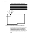
If the CSA 803C powersĆon (the ON/STANDBY light is on), but the display
gives scrambled information or none at all, then the CRT and A8 CRT Driver
board are suspect. The following two procedures help you determine whethĆ
er the A15 MMU board or one of the CRT units, (either the CRT, the A7 CRT
Socket board or the A8 CRT Driver board) is at fault.
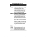
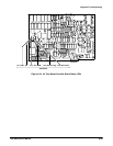
H With the power off (ON/STANDBY switch to STANDBY), remove the top
cover, then turn the power on. Observe the two LEDs on the A15 MMU
board and those on the A17 Executive Processor board in the card
cage. These LEDs should flicker on and off until the diagnostic tests are
complete and then all turn off. If any of these LEDs remain lit, it indicates
a problem with the board on which the LED resides. If all LEDs turn off,
then the CRT, A7 CRT Socket board, or the A8 CRT Driver board is
suspect.
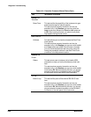
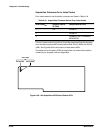
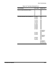
H With the power off, connect a test terminal (ANSI 3.64Ćcompatible) to the
CSA 803C using an RSĆ232ĆC cable. Touch the screen through the full
powerĆon cycle to force a diagnostic error so the instrument enters
Extended Diagnostics. On the test terminal, type T to display the EXĆ
TENDED DIAGNOSTICS menu on the terminal display. If the displayed
errors are only for the front panel touch screen, then the CRT, the A7
CRT Socket board, or the A8 CRT Driver board is at fault. Note any other
errors and use Table 6Ć5, earlier in this section, to identify the suspect
subsystem.
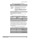
This board is implicitly verified; that is, if all the other FRUs pass diagnostic
testing, then you can assume that the A13 Mother board is operating corĆ
rectly as well.
CRT, A7 CRT Socket
Board, or A8 CRT
Driver Board
A13 Mother Board