


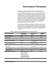
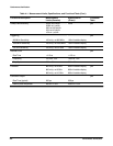

Block Diagram Descriptions
Theory of Operation
3Ć26
Battery Backup
This circuit provides standby power to the nonĆvolatile RAM (NVRAM) during
the poweredĆoff periods of the CSA 803C.
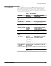
The A19 Strobe/TDR buffer board is comprised of three main circuits:
H Strobe sense select circuitry
H Strobe deskew circuitry
H TDR buffer and level shift circuitry
See Figure 9Ć12 for a block diagram of this board.
Strobe Sense Select
This circuitry consists of three signal diodes (these diodes are normally off).
The diodes carry the two sampling signals (J3A, J4A) from the two sampling
heads and the reference strobe signal. When a particular diode is biased on,
it allows the selected strobe sense signal to continue out of jumper J32.
Strobe Deskew
This circuit corrects the time delay between the sampling strobe signals
which may occur from the mismatch in the external cabling or in the internal
cables that distribute the strobe. The repositioning is done with the strobe
deskew voltages, which are DC control voltages found on jumper J34.
(Power is also supplied to this board through this jumper.) The strobe desĆ
kew voltages are generated on the A1 M/F Strobe Drive board and are
controlled by the microprocessor on the A5 Time Base/Controller board. The
sampling strobe alignment is checked by routing the strobe sense signals to
the A5 Time Base/Controller board where the microprocessor measures and
adjusts the time alignment of each sampling head.
TDR Buffer and Level Shift
This circuitry consists of an ECL buffer and four dualĆtransistors that levelĆ
shift the TDR signal for proper drive of the TDR step generators in the samĆ
pling heads.
A19 Strobe/TDR
Buffer Board