


Corrective Maintenance
CSA 803C Service Manual
6Ć57
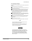
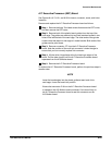
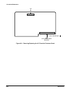
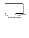
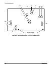
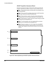
A19 Strobe/TDR Buffer Board
Removal and replacement steps are listed below. See Figures 6Ć23, 6Ć26,
and 6Ć32 for connector, screw, and index locations.
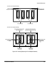
ăStep 1:ăRemove the Acquisition unit and position the Acquisition unit in
the upright position.
ăStep 2:ăRemove the two Torx head screws on each black retaining
brace located at the top of the Acquisition unit to remove these braces.
ăStep 3:ăRemove connectors J3A, J4A, J1B, J2B, J3C, J4C, J29A, J30A,
J32, J33A, J33B, and J34 from the A19 Strobe/TDR Buffer board.
NOTE
Record the positions of the connectors and the receptacles to
ensure that the connectors and receptacles can be correctly reĆ
placed.
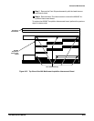
ăStep 4:ăRemove J10 from the A26 M/F Acquisition Interconnect board.
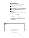
ăStep 5:ăRemove the two Torx head screws on the bottom of the A19
Strobe/TDR Buffer board, and gently pull out the board.
To replace the A19 Strobe/TDR board, perform the previous steps in reverse
order.