


Corrective Maintenance
Maintenance
6Ć76
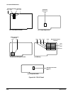
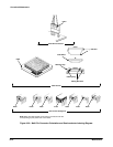
triangle on the multiĆpin holder is determined by the index (triangle, dot or
square) printed on the circuit board. Most boardĆmounted connectors have
a square pad for pin 1. (See Figure 6Ć32.)
NOTE
Match the index triangles on the multiĆpin connectors with the
corresponding square pads on the circuit board.
Some multiĆpin connectors are keyed by a gap between the pin 1
and 3 positions in the holder. (A small plastic plug covers the pin 2
position on the end of the holder.) There is a corresponding gap
between pins 1 and 3 on the circuit board.
Align the plug in the multiĆpin holder with the gap between the
circuit board pins. The connector is then ready to be installed.
Many of the larger, multiĆpin ribbon connectors have a red, blue, or other
contrasting color line along one side of their attached wire cables. This line
indicates the location of pins 1 and 2 and also the location of the correĆ
sponding triangle index mark on the connector.
Some of the grayĆcolored ribbon cables may have the number of their
connectors stamped on them.
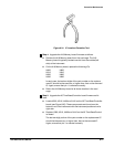
The ribbon connectors have the following two functions:
H to provide a strain relief for the wire connections. The wire ribbon is
wrapped around a bar between the wire connections and the top of the
connector. Strain is then felt between the wires and the top of the conĆ
nector. This relieves most of the strain which would otherwise be felt on
the wire connections.
H to provide a pullĆtab to ease disconnection. The pullĆtab is attached
inside the connector. When the tab is pulled, even pressure is applied
across the connector. The connector then separates from its holder
easily.
NOTE
To remove these ribbon connectors, grasp the pullĆtab (fastened
into the connector, if there) and pull it loose from the holder.
If there isn't a pullĆtab present in the connector, grasp the ends of
the connector, instead, and pull it straight out from the connector
socket.