


Corrective Maintenance
Maintenance
6Ć42
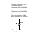
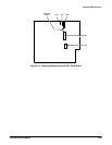
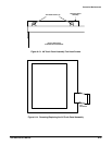
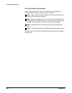
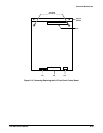
A10 Front Panel Control Board
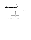
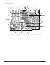
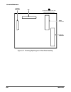
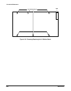
Removal and replacement steps are listed below. See Figures 6Ć5, 6Ć11,
6Ć15 and 6Ć32 for connector, screw, and index locations.
ăStep 1:ăRemove the CRT shield. (Refer to Cathode Ray Tube Removal
in this section, beginning at Step 4.)
ăStep 2:ăRemove connectors J72, J73, J74, and J75 from the A10 Front
Panel Button board. Note the position of the multiĆpin connectors' index
triangles to ensure that the connectors can be correctly replaced.
ăStep 3:ăRemove the two Torx head screws at the upper edge of the
board.
ăStep 4:ăLift the board away from the guides at its bottom and remove it.
To replace the A10 Front Panel Control board, perform the previous steps in
reverse order.