


Block Diagram Descriptions
CSA 803C Service Manual
3Ć13
The A8 CRT Driver board consists of the following circuits:
H Horizontal sweep circuitry
H Vertical sweep circuitry
H High voltage and grid voltage generator circuitry
H Degauss circuit
H Beam current limit circuit
H Grid bias circuit
The A8 CRT Driver board circuitry drives the raster scan CRT. The VIDEO
and SYNC signals from the A15 MMU board generate the ZĆaxis signal,
sweep signals, and grid bias voltages for the CRT.
See Figure 9Ć6 for a block diagram of this board.
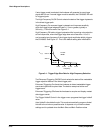
Horizontal Sweep
This circuit generates the sweep current for the horizontal deflection yoke.
The horizontal driver includes an oscillator, a voltage ramp generator, a
highĆgain amplifier, and a flyback generator. These components provide
sweep synchronization, horizontal deflection, and linearity.
The horizontal adjustments, HĆSIZE, HĆPOS, and HĆLIN, allow you to optiĆ
mize the appearance of the display.
Vertical Sweep
This circuit produces a deflection current that sweeps the video beam from
the bottom to the top of the CRT. This circuit also produces a flyback signal
to the flyback transformer that is in parallel with the deflection yoke.
The vertical adjustments, VERT SIZE and VERT POS, set the vertical size
and position of the display.
High Voltage and Grid Voltage Generator
This circuit includes the flyback transformer that generates the 16 kV CRT
anode potential and other bias voltages. This transformer is coupled and
synchronized with the vertical deflection system.
The SCREEN adjustment provides the cutoff point; that is, the point where
no information is visible on the display screen. The FOCUS adjustment
provides manual focusing of the display image.
A8 CRT Driver Board