


CSA 803C Service Manual
4Ć1
Performance Verification
This section contains procedures to check electrical specifications and
examine measurement limits listed in Table 4Ć1. Use these procedures to
check the CSA 803C following repair, or to verify that the CSA 803C meets
specifications. To functionally test the CSA 803C, simply perform the proceĆ
dures which have a yes" indication in the Functional Tests column listed in
Table 4Ć1. The Specifications or Measurement Limits are given at the beginĆ
ning of each procedure. Adjustment procedures are included in the AdjustĆ
ments section. Refer to the CSA 803C Communications Signal Analyzer User
Manual for more information about specifications and CSA 803C operation.
The Setup in each procedure provides information concerning test equipĆ
ment setup or interconnection. Refer to Table 4Ć2 for more information
concerning test equipment used in the setups.
Most Performance Verification and Adjustment procedures can be run in any
order. However, the Sampling Head Calibration must always precede other
procedures which use an operational sampling head (i.e., does not apply to
procedures using the Calibration Head). Also, if different sampling heads are
used, then sampling head calibration is required for each additional samĆ
pling head.
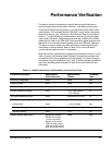
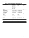
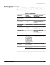
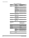
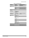
TableĂ4Ć1:ăMeasurement Limits, Specifications, and Functional Tests
Procedure Description
Measurement
Limits (Examine)
Specifications
(Check)
Functional
Tests
PowerĆOn Diagnostics none none yes
Sampling Head none none yes
Extended Diagnostics none none yes
Vertical Reference Voltage none +5 V ±200 mV and
-5 V ±200 mV
no
Horizontal Reference Clock none 200,000 kHz ±5 kHz no
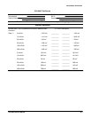
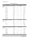
Vertical Accuracy
Vertical Gain none ±1.0% full scale yes
Offset Accuracy none ±2 mV yes
Vertical Linearity none ±1% no
System Vertical RMS Noise 200 mV at 2 mV/div
500 mV at 5 mV/div
1 mV at 10 mV/div
632 mV at 20 mV/div
1.58 mV at 50 mV/div
3.16 mV at 100 mV/div
6.32 mV at 200 mV/div
none yes