


Block Diagram Descriptions
Theory of Operation
3Ć16
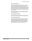
The A12 Rear Panel assembly links the oscilloscope to other devices. This
assembly contains connectors for the following ports:
H One GPIB Port
H One RSĆ232ĆC Port
H One Printer Port (Centronics style)
The A12 Rear Panel assembly is controlled from the A14 Input/Output (I/O)
board through a 40Ćwire cable. This cable contains the following signals:
H EightĆbit bidirectional data bus
H FourĆbit address bus
H Four interrupt lines
H GPIB DMA request and grant lines
H Four device control lines
H Assorted power supply and ground lines
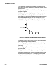
See Figure 9Ć7 for a block diagram of this assembly.
GPIB Data and Address Bus
This bus drives the GPIB controller directly. Control signals DBIN and WR
are used by the GPIB controller to determine if the microprocessor is trying
to read from it or write to it. The interrupt controllers in the A17 Executive
Processor board monitor this interrupt line and will signal the microprocesĆ
sor to service the GPIB controller. In order to communicate with the microĆ
processor, the GPIB controller requires that at least one of the following
conditions occurs:
H the receiver section of the GPIB controller has a byte of data (Inbyte
Register) from the GPIB bus that the microprocessor needs to read
H the transmitter section register (Outbyte Register) is empty and is ready
to receive another byte of data
H the status of the GPIB bus or the GPIB controller has changed and the
microprocessor has to be notified
On the opposite side of the GPIB controller is another bus system. This
other bus system includes an 8Ćbit data bus which accesses a bidirectional
GPIB data buffer and an eightĆbit control bus which accesses a GPIB control
driver. The GPIB bus is connected to the opposite side of the buffer and
control driver. These two devices are specially designed to be TTL signalĆlevĆ
el compatible on the bus side of the buffer driver.
The states of three control signals from the GPIB controller, SRQ, NRFD, and
NDAC, are monitored and displayed on the rear panel of the CSA 803C.
These LEDs show the state that the GPIB controller is in, not the state of the
GPIB bus.
A12 Rear Panel
Assembly