


Performance Tests
CSA 803C Service Manual
4Ć31
This procedure uses the RMS measurement function to measure the noise
on the trace from a sampling head compartment.
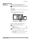
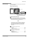
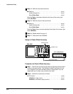
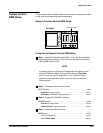
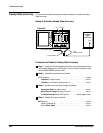
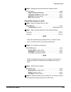
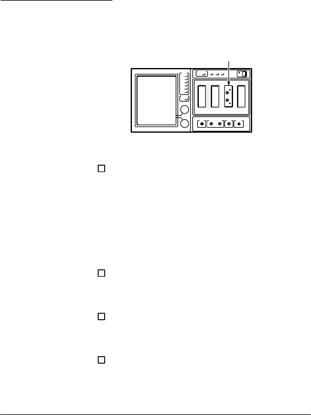
Setup to Examine Vertical RMS Noise
CSA 803C
Calibration Head
Procedure to Examine Vertical RMS Noise
ăStep 1:ăInstall the Calibration Head (067-1413-00) into the position
shown in the setup diagram. If the unit was in standby mode, set the
ON/STANDBY switch to ON.
NOTE
If powering up from a cold start, the diagnostics will report an error
using the Calibration Head. The report will indicate a Time Base
error. To clear this, exit the diagnostics. Then, ignore the subseĆ
quent time base calibration failure notice and continue with the
following steps.
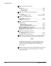
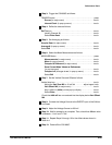
ăStep 2:ăInitialize the mainframe as follows:
UTILITY button press...........................................
Initialize (in major menu) touch..............................
Initialize (in verification popĆup menu) touch..................
ăStep 3:ăTrigger the CSA 803C as follows:
TRIGGER button press.........................................
Source (in major menu) touch...............................
Internal Clock (in popĆup menu) touch.......................
ăStep 4:ăIdentify the trace as follows:
Def Tra icon touch.............................................
Identify Channel (1) touch...................................
Select Enter Desc touch....................................
System Vertical
RMS Noise