


Corrective Maintenance
CSA 803C Service Manual
6Ć9
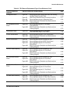
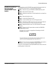
TableĂ6Ć2:ăFRU Removal/Replacement Figure Cross Reference (Cont.)
FRU to be Removed/
Replaced
Figures to Reference During Removal Page
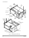
A4 Regulator Board Figure 6Ć2 Removing the Power Supply Rear Plate, Fan Housing,
and Rear Panel Connector Plate 6Ć16........................
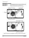
Figure 6Ć3 A2A2 Control Rectifier Board Connectors Locations 6Ć17.......
Figure 6Ć9 Removing/Replacing the A4 Regulator Board 6Ć34.............
Figure 6Ć32 MultiĆPin Connector Orientation and Semiconductor
Indexing Diagram 6Ć74.....................................
A5 Time Base/Controller
Board
Figure 6Ć10 Removing/Replacing the A5 Time Base/
Controller Board 6Ć36......................................
Figure 6Ć32 MultiĆPin Connector Orientation and Semiconductor
Indexing Diagram 6Ć74.....................................
A6 Calibrator Board Figure 6Ć10 Removing/Replacing the A5 Time Base/
Controller Board (Steps 1 and 2 only) 6Ć36...................
A7 CRT Socket Board Figure 6Ć11 Removing/Replacing the A7 CRT Driver Board 6Ć38............
Figure 6Ć32 MultiĆPin Connector Orientation and Semiconductor
Indexing Diagram 6Ć74.....................................
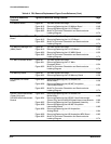
A8 CRT Driver Board Figure 6Ć5 Removing/Replacing the Cathode Ray Tube 6Ć24..............
Figure 6Ć12 Removing/Replacing the A8 CRT Driver Board 6Ć39............
Figure 6Ć15 Removing/Replacing the A10 Front Panel
Button Board 6Ć43.........................................
Figure 6Ć32 MultiĆPin Connector Orientation and Semiconductor
Indexing Diagram 6Ć74.....................................
A9 Touch Panel Assembly Figure 6Ć5 Removing/Replacing the Cathode Ray Tube 6Ć24..............
Figure 6Ć15 Removing/Replacing the A10 Front Panel
Button Board 6Ć43.........................................
Figure 6Ć32 MultiĆPin Connector Orientation and Semiconductor
Indexing Diagram 6Ć74.....................................
A10 Front Panel Control
Board
Figure 6Ć5 Removing/Replacing the Cathode Ray Tube 6Ć24..............
Figure 6Ć15 Removing/Replacing the A10 Front Panel
Button Board 6Ć43.........................................
Figure 6Ć32 MultiĆPin Connector Orientation and Semiconductor
Indexing Diagram 6Ć74.....................................
A11 Front Panel Button
Board
Figure 6Ć5 Removing/Replacing the Cathode Ray Tube 6Ć24..............
Figure 6Ć15 Removing/Replacing the A10 Front Panel
Button Board 6Ć43.........................................
Figure 6Ć16 Removing/Replacing the A11 Front Panel
Button Board 6Ć44.........................................
Figure 6Ć32 MultiĆPin Connector Orientation and Semiconductor
Indexing Diagram 6Ć74.....................................
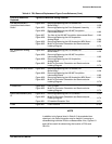
A12 Rear Panel Assembly Figure 6Ć5 Removing/Replacing the Cathode Ray Tube 6Ć24..............
Figure 6Ć17 Removing/Replacing the A12 Rear Panel Assembly 6Ć46.......
Figure 6Ć32 MultiĆPin Connector Orientation and Semiconductor
Indexing Diagram 6Ć74.....................................