


Diagnostic Troubleshooting
CSA 803C Service Manual
6Ć97
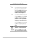
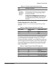
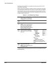
TableĂ6Ć12:ăExecutive Processor Manual Tests (Cont.)
Test Verification Procedure
GPIB
ąInrpt Reset
ąReset Status
ąData Lines
ąInterrupt
These tests verify the Executive processor interface to
the internal GPIB circuitry. The major external GPIB
functions are not tested.
This test requires operator interaction and can be
executed only in the Routine popĆup menu with the All
and Loop modes set to Off. Before executing this test,
you should disconnect the GPIB connector from the
instrument.
Display Subsystem Error Index Codes
The Display subsystem error index codes and suspect FRUs are listed in
Table 6Ć13.
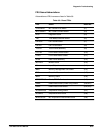
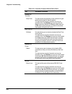
TableĂ6Ć13:ăDisplay Processor Kernel Error Index Codes
Error Index
hex
Suspect Hybrid/
IC FRUs
Suspect Board FRUs
1-4 FW MMU
5-7 MMU
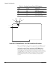
The name of the first Display kernel test that fails is displayed on the screen.
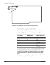
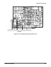
The Display processor error index code is read from the A15 MMU board
test points DIAG0 (LSB) to DIAG2 (MSB). The bits are high (+5 V) true.
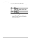
The status LEDs (DS201 and DS200) on the A15 MMU board will flash while
the Kernel diagnostic tests are executing. If a kernel failure is detected, then
one or both LEDs will remain on. Table 6Ć14 lists the various LED configuraĆ
tions and their significance. See Figure 6Ć34 for the location of these test
points and status LEDs.
TableĂ6Ć14:ăDisplay Processor Status LED Configuration
DS200
DS201 Significance
ON ON PowerĆOn
ON OFF Kernel Tests Executing
OFF ON Kernel Tests Failed
OFF OFF Kernel Tests Finished