


Corrective Maintenance
Maintenance
6Ć38
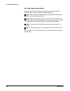
ăStep 8:ăRemove the single Torx head screws that secures the transĆ
former, on the A8 CRT Driver board, to the instrument chassis. This
screw is located at the rear of the transformer. The A8 CRT Driver board
is now not attached to the instrument chassis.
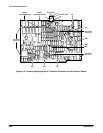
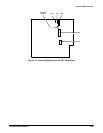
ăStep 9:ăRemove connectors J52, J56, and J57 from the A8 CRT Driver
board. Note the position of the multiĆpin connectors' index triangles to
ensure that you can correctly replace these connectors.
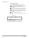
ăStep 10:ăLift the A8 CRT Driver board partially out of the instrument
chassis.
ăStep 11:ăRemove connectors J54 and J55 from the A8 CRT Driver
board. Note the position of the multiĆpin connectors' index triangles to
ensure that you can correctly replace these connectors.
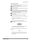
ăStep 12:ăRemove the A8 CRT Driver board and the A7 CRT Socket
board.
ăStep 13:ăUnsolder the two wires that connect the A8 CRT Driver board
to the A7 CRT Socket board (the two boards are now separated).
To replace the A8 CRT Driver board and the A7 CRT Socket board, perform
the previous steps in reverse order.
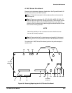
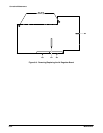
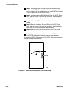
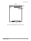
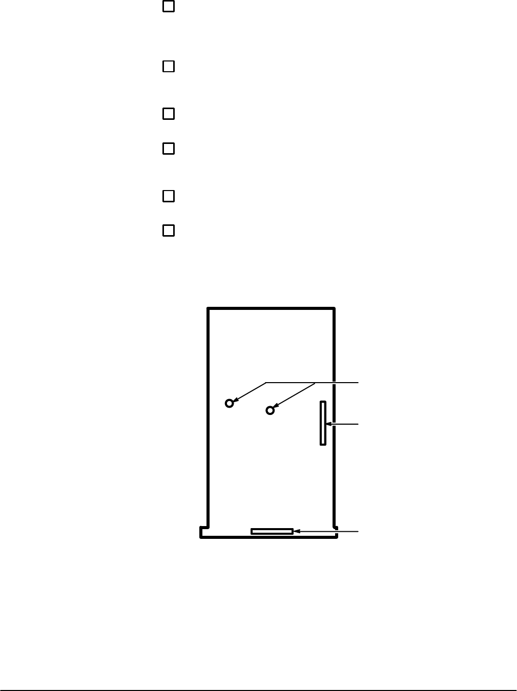
J53
J56
Solder Points
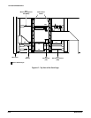
Figure 6Ć11:ăRemoving/Replacing the A7 CRT Socket Board