


Corrective Maintenance
CSA 803C Service Manual
6Ć33
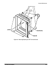
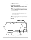
A4 Regulator Board
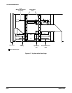
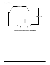
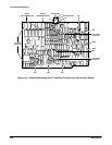
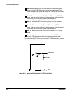
Removal and replacement steps are listed below. See Figures 6Ć2, 6Ć3, 6Ć9,
and 6Ć32 procedures for removal for connector, screw, and index locations.
ăStep 1:ăRemove the Power Supply module. (See Power Supply Module
Removal in this section.)
ăStep 2:ăSet the instrument upright (if not already in this position).
ăStep 3:ăRemove connectors J57 and J60 from the A4 Regulator board.
Note the position of the multiĆpin connectors' index triangles to ensure
that the connectors can be correctly replaced.
ăStep 4:ăRemove the two Torx head screws from the metal heat sink
attached to the rear of this board).
NOTE
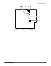
The A4 Regulator board is not attached to the chassis. However, it
remains connected to the A3 M/F Power Connect board through
interconnecting pins.
ăStep 5:ăCarefully remove the J95 and J96 pins from the A4 Regulator
board by pulling the A4 Regulator board toward the rear.
ăStep 6:ăRemove the A4 Regulator board.
To replace the A4 Regulator board, perform the previous steps in reverse
order.
NOTE
Match the index triangles on the multiĆpin connectors with the
corresponding square pads on the circuit board.