


Diagnostic Troubleshooting
CSA 803C Service Manual
6Ć93
Executive Subsystem Error Codes
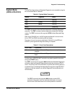
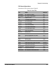
Error index codes for the Executive subsystem are listed in Table 6Ć10 along
with the suspected FRUs.
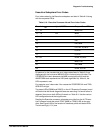
TableĂ6Ć10:ăExecutive Processor Kernel Error Index Codes
Error Index
hex
Hybrid/IC FRUs Suspect Board FRUs
1F - 1D MEM, EXP
1C-19 FW MEM
18-16 IO, EXP
15 EXP
14 EXP, MEM
13 FPCTRL, IO, MPU
12 IO, EXP
11 IO, EXP
10-0E REAR, IO, MPU
0D MMU, EXP
0C EXP, MEM
0B REAR, IO, EXP
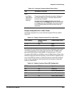
Bit patterns for the hexadecimal error index codes listed in Table 6Ć10 are
displayed with the front panel MENUS LEDs in bottomĆtoĆtop bit order. The
STORE/RECALL label represents the MSB (most significant bit) and the
WAVEFORM label represents the LSB (least significant bit). When lit, the
LEDs represent a one.
For example, error index code 12
hex
causes the STORE/RECALL and TRIGĆ
GER LEDs to light.
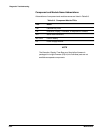
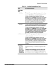
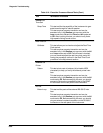
The status LEDs (DS306 and DS307) on the A17 Executive Processor board
will flash while the Kernel diagnostic tests are executing. If a kernel failure is
detected, then one or both LEDs will remain on. Table 6Ć11 lists the various
LED configurations and their significance.
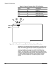
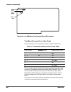
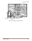
Reading the Executive processor subsystem error bits from the A17 ExecuĆ
tive Processor board test points TP201 (MSB) to TP205 (LSB) is also posĆ
sible. See Figure 6Ć33 for the location of these test points and status LEDs.
The bits are high (+5 V) true.