


Corrective Maintenance
CSA 803C Service Manual
6Ć31
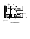
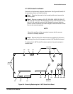
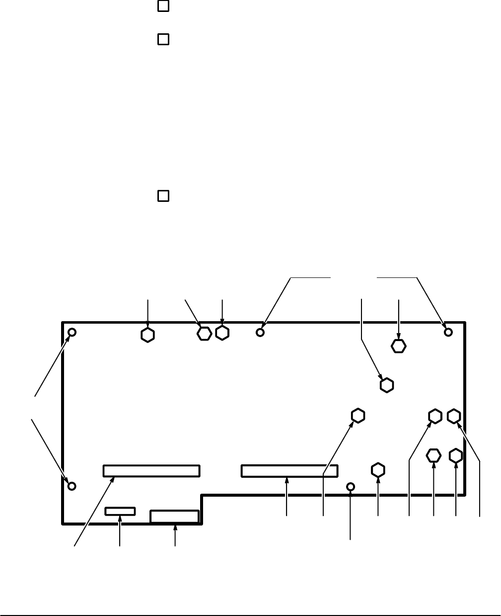
A1 M/F Strobe Drive Board
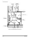
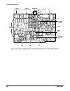
Removal and replacement steps are listed below. See Figures 6Ć8 and 6Ć32
for connector, screw, and index locations.
ăStep 1:ăPlace the instrument in the inverted position and remove the
bottom panel.
ăStep 2:ăRemove connectors J16, J27, J28, J33A, J33B, J35, J36, J37,
J38, and J39 from the A1 M/F Strobe Drive board. Then remove connecĆ
tors J10, J18, and J34 from the A1 M/F Strobe Drive board. Note the
position of the connectors and index triangles to ensure that the connecĆ
tors can be correctly replaced.
NOTE
Record the positions of the connectors to ensure that the connecĆ
tors can be correctly replaced.
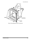
ăStep 3:ăRemove the five Torx head screws and carefully lift the board,
removing it from the J19 connector on the A1 M/F Strobe Drive board.
To replace the A1 M/F Strobe Drive board, perform the previous steps in
reverse order.
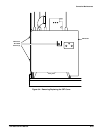
J16
J15
J10 J34 J19
J18 J28 J17
Torx Head
Screws (2)
Torx Head
Screws (2)
Torx Head
Screw (1)
J36 J37
J33A J33BJ38 J39
J27
Figure 6Ć8:ăRemoving/Replacing the A1 M/F Strobe Drive Board