


Corrective Maintenance
Maintenance
6Ć40
A9 Touch Panel Assembly
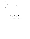
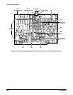
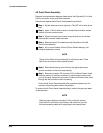
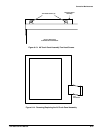
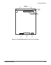
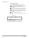
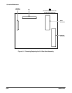
Removal and replacement steps are listed below. See Figures 6Ć5, 6Ć15 and
6Ć32 for connector, screw, and index locations.
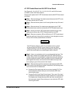
Remove and replace the A9 Touch Panel assembly as follows:
ăStep 1:ăSet the instrument on its right side. (The CRT will now be at the
top.)
ăStep 2:ăUse a 1/16Ćinch Allen wrench to loosen the small Allen screws
in each of the two control knobs.
ăStep 3:ăSlowly remove the two control knobs so that you do not lose
the small Allen screws inside the knobs.
ăStep 4:ăRemove the two Torx head screws at the bottom of the A9
Touch Panel Assembly.
ăStep 5:ăLift up on the bottom of the A9 Touch Panel Assembly, and
swing the assembly outward.
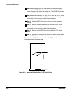
NOTE
The top of the A9 Front Panel Assembly is held by two tabs. These
tabs fit into two slots in the frontĆpanel chassis.
ăStep 6:ăRemove the black ground wire from the quickĆdisconnect
ground connector on the front panel casting.
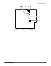
ăStep 7:ăRemove connector J73 from the A10 Front Panel Control board.
Note the position of multiĆpin connector's index triangle to ensure that
you can correctly replace this connector. Carefully remove the wire cable
through the slot provided in the front casting.
Cover the A9 Touch Panel Assembly with protective material once it is
removed, since the plastic exterior may scratch.
To replace the A9 Touch Panel Assembly board, perform the previous steps
in reverse order.
NOTE
Feed any slack cable from connector J73 to inside the chassis
(near the A10 Front Panel Control board). Be careful not to pinch
the interconnecting cable while replacing the front panel bezel.