


Corrective Maintenance
CSA 803C Service Manual
6Ć21
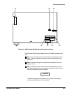
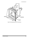
ăStep 7:ăSet the A9 Touch Panel Assembly aside. To avoid stressing the
ribbon cable that is still connected to the A9 Touch Panel Assembly, and
to keep the assembly from cluttering your work space, place the A9
Touch Panel Assembly on top of the sampling head compartments. Do
not damage the A9 Touch Panel Assembly when placing it on top of the
sampling head plugĆin compartments.
ăStep 8:ăCarefully set the instrument on its left side.
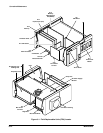
ăStep 9:ăRemove the two plastic circuit board guides from the top of the
card cage.
ăStep 10:ăRemove the two Torx head screws that secure the A7 CRT
Socket board cover. Use a short Torx head screwdriver to remove the
rearĆmost Torx head screw.
ăStep 11:ăRemove the A7 CRT Socket board cover.
ăStep 12:ăSlowly pull the A7 CRT Socket board toward the rear of the
instrument to remove the A7 CRT Socket board from the CRT.
NOTE
When reattaching the A7 CRT Socket board to the CRT, align the
pins of the CRT to the receptacles on the A7 CRT Socket board.
Then, slowly push the pins into the receptacles.
Do not force the connector into place; doing so can bend or break
some of the pins. If the pins do not slide easily into the receptacles,
then pull the A7 CRT Socket board away from the CRT, and realign
the A7 CRT Socket board to the CRT.
WARNING
The CRT anode voltage is 16 kV. To avoid electric shock, ground
the anode lead from the CRT to the chassis to remove any stored
charge remaining in the CRT. Wait approximately ten minutes. Then,
ground the anode load to the chassis again.
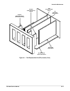
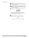
ăStep 13:ăRemove connector J54 from the A8 CRT Driver board. Note
the position of the multiĆpin connector's index triangle to ensure that you
can correctly replace the connector.
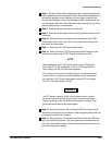
ăStep 14:ăRemove the four Torx head screws that secure the CRT to the
top of the instrument chassis. Two of the screws are removed from the
front of the front panel chassis, and two of the screws are removed from
behind the front panel casting.