Corrective Maintenance
Maintenance
6Ć22
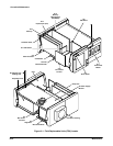
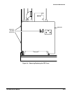
ăStep 15:ăRemove the top CRT support bar from the instrument. The
CRT support bar is unattached once the four Torx head screws securing
the top of the CRT are removed.
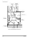
ăStep 16:ăRemove the four Torx head screws that secure the CRT to the
bottom of the instrument chassis. Two of the screws are removed from
the front of the front panel chassis, and two of the screws are removed
from behind the front panel casting.
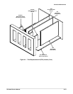
ăStep 17:ăRemove the bottom CRT support bar from the instrument.
CAUTION
Once the four Torx head screws are removed from the bottom of
the CRT, the CRT is not attached to the instrument. Use care to not
damage the CRT while it is loose in the instrument.
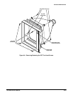
ăStep 18:ăSlowly pull the CRT out of the front panel chassis.
To replace the CRT, perform the previous steps in reverse order.
NOTE
Replacing the CRT will require that the instrument be readjusted.


