


Block Diagram Descriptions
Theory of Operation
3Ć12
Memory Management Unit (MMU) Interface
This circuit interfaces the Time Base/ Controller to the EXP and the WaveĆ
form Memory. This interface allows the EXP to send commands to the microĆ
processor through the Time Base/Controller and provides the path for
waveform transfers from the Acquisition system to the Waveform Memory.
The A7 CRT Socket board is an interface from the A15 MMU board to the
CRT. The A7 CRT Socket board consists of the following circuits:
H Red, Green, and Blue video amplifiers
H RED, GREEN, and BLUE cutoff adjustments
H CONVERGENCE adjustment
See Figure 9Ć5 for a block diagram of this board.
Red, Green, and Blue Video Amplifiers
These three circuits are identical high speed video amplifiers that drive the
three cathodes (R, G, and B; red, green, and blue, respectively) of the CRT.
Each of the three colors can be programmed to display 64 different levels.
This yields a possible 262,144 colors, of which eight can be displayed on
the screen at any time.
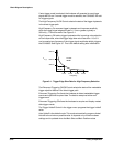
Red, Green, and Blue Adjustments
These three potentiometers control the cutoff point; that is, the point at
which a certain color becomes invisible.
Convergence Adjustment
This potentiometer controls the vertical convergence of the red, green, and
blue deflection beams.
A7 CRT Socket Board