


Adjustments
Adjustment Procedures
5Ć6
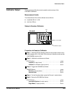
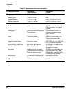
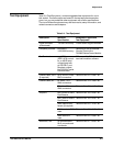
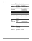
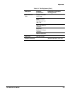
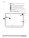
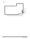
Some procedures begin with a setup illustration that shows what test equipĆ
ment is needed and how to connect it. The other procedures require only a
calibrated SDĆSeries Sampling Head. Refer to Table 5Ć2 (Test Equipment) on
the preceding pages for an example of the test equipment for each proceĆ
dure.
Conventions in this Manual
In these procedures, the following conventions are used:
H CAPITAL letters within the body of text identify front panel controls,
indicators, and connectors on the CSA 803C (for example, MEASURE)
and sampling head.
H Bold letters identify menu labels and display messages.
H Initial Capital letters identify connectors, controls, and indicators (for
example, On) on associated test equipment.
H In some steps, the first word is italicized to identify a step that contains a
performance verification and an adjustment instruction. For example, if
Check is the first word in the title of a step, an electrical specification is
checked. If Adjust appears in the title, the step involves an electrical
adjustment. If Examine is the first word in the title, the step concerns
measurement limits that indicate whether the CSA 803C is operating
properly; these limits are not to be interpreted as electrical specificaĆ
tions.
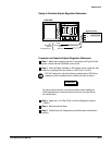
Menu Selections and Measurement Techniques
Details on measurement techniques and instructions for making menu
selections are generally not included in these procedures. Comprehensive
descriptions of menus and CSA 803C features are located in the CSA 803C
Communications Signal Analyzer User Manual.
User Manual
Reviewing the CSA 803C Communications Signal Analyzer User Manual is
strongly recommended to familiarize the firstĆtime user with CSA 803C
controls and features.
Using These
Procedures