


CSA 803C Service Manual
3Ć3
System Functional Overview
This section describes the major functional blocks of the CSA 803A (see
Figure 9Ć1).
The CSA 803C contains an Acquisition system, which supports two dualĆ
channel sampling heads and contains two data acquisition and measureĆ
ment channels. Additionally, two powerĆonly slots are provided.
Since the Acquisition system supports four input channels (two dualĆchannel
heads) and contains only two measurement channels, the four input chanĆ
nels are multiplexed into the two measurement channels through an analog
multiplexer. Either one of the sampling head input channels can be indepenĆ
dently connected to either of these two measurement channels.
Several calibration signals are also supplied to each multiplexer, although
these signals are used only for selfĆtests and diagnostics.
The Strobe Distribution block acts as an interface between the Time Base/
Controller and the Acquisition systems.
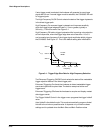
The Time Base/Controller generates a strobe pulse that is regenerated by
the Strobe Distribution block to drive all the sampling heads in parallel.
The Time Base/Controller block is comprised of the following circuits:
H a microprocessor with local RAM and ROM
H the time base and trigger circuits
H interfaces to the memory management unit (MMU) and Acquisition
systems
The Trigger Select block selects the desired trigger signal to be sent to the
Time Base/Controller block.
Acquisition System
Block
Strobe Distribution
Block
Time Base/Controller
Block
Trigger Select Block