


Adjustments
CSA 803C Service Manual
5Ć13
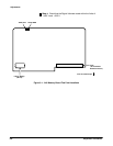
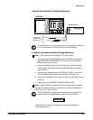
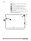
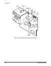
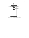
This procedure shows the setup and lists the steps to examine and adjust
the A7 CRT Socket board and the A8 CRT Driver board (see Figures 5Ć4 and
5Ć5).
The adjustments in this procedure only affect the visual aspects of
the CRT display and you should only perform these adjustments
when the CRT, A7 CRT Socket board, or A8 CRT Driver board comĆ
ponents are replaced. These adjustments do not affect CSA 803C
accuracy since all measurements are made on the acquired data,
not the displayed data. Unless alignment or brightness difficulties
are apparent, proceed to the Real Time Clock adjustment proceĆ
dure.
For all Examine steps in this procedure, if the display parameter examined is
within the stated limits, then do not perform the Adjust step following that
Examine step. Instead, proceed to the step following the Adjust step.
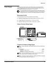
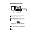
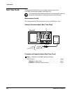
Measurement Limits
The measurement limits are set on the CRT as follows:
H The display must be visible (not cut off).
H The red, green, and blue traces must not be separated.
H Focus is adjusted for minimum line width.
H Vertical size is adjusted to align the corners of the grid pattern with the
tic marks on the edges of the front panel bezel.
H Horizontal size is adjusted to align the corners of the grid pattern with
the tic marks on the top and bottom edges of the front panel bezel, and
the horizontal linearity is adjusted for uniform grid box length.
H Horizontal linearity is adjusted for optimum appearance using an interĆ
nally generated grid pattern.
H Red, green, and blue colors must have optimum white to gray scale
linearity.
H Red Display, Green Disply, and Blue Display in Extended Diagnostics
must not contain severe color impurities.
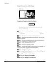
Display