


Adjustments
Adjustment Procedures
5Ć16
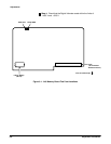
ăStep 26:ăExamine that the color scale is white at the top, gray at the
bottom, and the background on the right side of the display is cut off
(that is, the vertical raster lines are not visible on the right side of the
display).
If the gray scale meets the previous conditions, do not perform the
adjustments in Steps 27, 28, and 30. Proceed to Step 31.
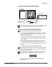
ăStep 27:ăAdjust RED, R200; GREEN, R201; and BLUE, R203; on the A7
CRT Socket board fully counterclockwise.
ăStep 28:ăAdjust SCREEN, located on the transformer that is mounted
on the A8 CRT Driver board, so that the bottom block of the gray scale
is visible but the background on the right side of the display is still cut
off.
ăStep 29:ăNote which color (red, green, or blue) appears most promiĆ
nently in the display. DO NOT adjust this color in the following step.
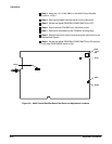
ăStep 30:ăAdjust RED, R200; GREEN, R201; or BLUE, R203; on the A7
CRT Socket board for a pure white to gray scale display. Only adjust the
colors that do not appear to be prominent. For example, if the display
appears to be more red, then adjust the GREEN and BLUE potentiomeĆ
ters.
NOTE
SCREEN may have to be adjusted slightly if any of the colors are
adjusted. If the vertical raster lines are visible in the background,
then adjust SCREEN so that the background is just cut off, but the
bottom gray box is still visible.
ăStep 31:ăTouch Exit to return to the Extended Diagnostic menu strucĆ
ture.
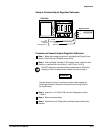
ăStep 32:ăTouch Red Display, and then touch Run.
ăStep 33:ăExamine the red display for any severe color impurities.
ăStep 34:ăTouch Exit to return to the Extended Diagnostics menu
structure.
ăStep 35:ăTouch Green Disply and then touch Run.
ăStep 36:ăExamine the green display for any severe color impurities.
ăStep 37:ăTouch Exit to return to the Extended Diagnostic menu strucĆ
ture.
ăStep 38:ăTouch Blue Display and then touch Run.
ăStep 39:ăExamine the blue display for any severe color impurities.