Corrective Maintenance
Maintenance
6Ć18
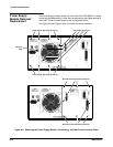
ăStep 4:ăRemove the wire connectors from the pins on the A2A2 Control
Rectifier board.
ăStep 5:ăRemove the chassis ground (greenĆyellow) wire that is conĆ
nected to the Power Supply module from the chassis of the instrument.
ăStep 6:ăRemove the Power Supply module.
To replace the Power Supply module, perform the previous steps in reverse
order.
NOTE
Align the metal guides on the top of the Power Supply module with
the grooves inside the upper part of the opening in the instrument.
Be careful not to pinch any wires or interconnecting cables while
installing the Power Supply module.


