3-48 FUEL SYSTEM (DFI)
Fuel Injectors (Service Code/Character-41, 42, 43, 44/InJ1, InJ2, InJ3, InJ4)
•
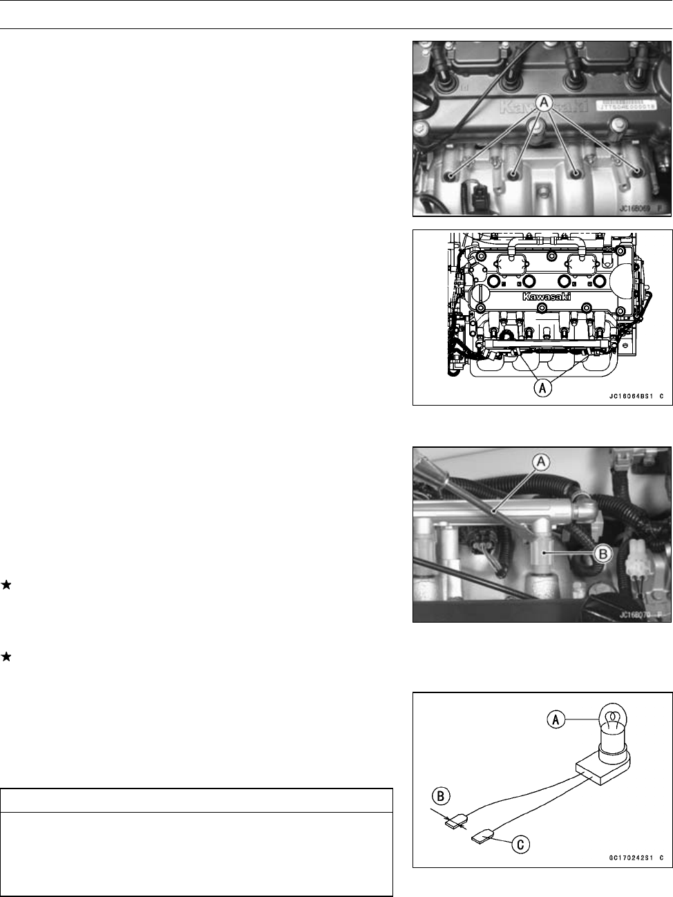
Replace the seals [A] with new ones.
•
Apply grease to the inside and outside of seals.
•
Install:
Delivery Pipe Assembly
Collars
•
Install the clamps [A] as shown.
•
Tighten:
Torque - Delivery Pipe Mounting Bolts: 7.8 N·m (0.80 kgf·m,
69 in·lb)
•
Install the fuel hoses (see Cable, Wire, and Hose Routing
section in Appendix chapter).
○
For JT1500-A2 model ∼; Replace the double spring
clamps with new ones. (see Fuel System Diagram)
Audible Inspection
•
Start the engine.
•
Apply the tip of a screwdriver [A] to the injector [B]. Put
the grip end onto your ear, and listen whether the injector
is clicking or not.
•
A sound scope can also be used.
•
Do the same for the other injector.
If all the injectors click at a regular intervals, the injectors
are good.
○
The click interval becomes shorter as the engine speed
rises.
If either injector doesn’t click, perform the “Injector Signal
Test” for injector operation.
Injector Signal Test
•
Prepare four test lights set with male terminals as shown.
Rating of Bulb [A]: 12 V, 3 ∼ 3.4 W
Terminal Width [B]: 1.8 mm (0.07 in.)
Terminal Thickness [C]: 0.8 mm (0.03 in.)
CAUTION
Do not use larger terminals than specified above. A
larger terminal could damage the injector main har-
ness connector (female), leading to harness repair
or replacement.


