


3-50 FUEL SYSTEM (DFI)
Fuel Injectors (Service Code/Character-41, 42, 43, 44/InJ1, InJ2, InJ3, InJ4)
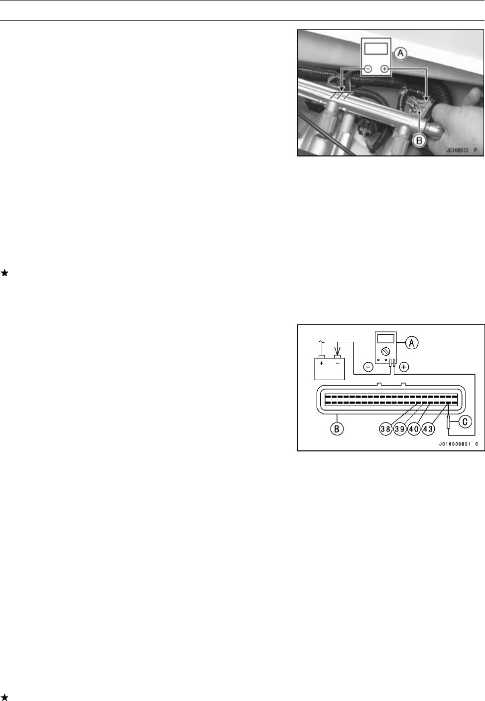
Injector Voltage Inspection
•
Turn the ignition switch OFF.
•
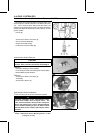
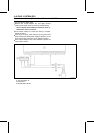
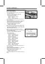
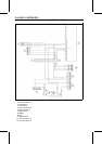
Connect a digital voltmeter [A] to the connector [B], with
the needle adapter set.
Special Tool - Needle Adapter Set: 57001-1457
Injector Power Source Voltage
Connector to Injector #1, #2, #3, #4
Meter (+) → R/Y lead
Meter (–) → Battery (–) Terminal
•
Turn the ignition switch ON and push the lanyard key un-
der the stop button.
•
Pushing the start button, run the engine 5 ∼ 6 seconds at
idling to measure the injector power source voltage.
○
Wait 15 seconds before using the starter again.
Power Source Voltage at Injector Connector
Standard:
Battery Voltage
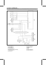
If the power source voltage is less than standard, check
the wiring (see Wiring Diagram in this section), relay
(Main Relay Inspection) and ECU power source (see
ECU Power Supply Inspection).
•
Remove the ECU. Do not disconnect the connector.
•
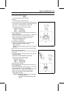
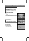
Connect a digital voltmeter [A] to the connector [B], with
the needle adapter set [C].
Special Tool - Needle Adapter Set: 57001-1457
Injector Output Voltage
Connections to Injector #1
Meter (+) → PU lead (terminal 43)
Meter (–) → Battery (–) Terminal
Connections to Injector #2
Meter (+) → O lead (terminal 38)
Meter (–) → Battery (–) Terminal
Connections to Injector #3
Meter (+) → BR lead (terminal 39)
Meter (–) → Battery (–) Terminal
Connections to Injector #4
Meter (+) → BL/Y lead (terminal 40)
Meter (–) → Battery (–) Terminal
•
Turn the ignition switch ON and push the lanyard key un-
der the stop button.
•
Pushing the start button, run the engine 5 ∼ 6 seconds at
idling to measure the output voltage.
○
Wait 15 seconds before using the starter again.
Output Voltage at Injector Connector
Standard:
about 9 V or more
If the output voltage is out of the standard, replace the
ECU.