FUEL SYSTEM (DFI) 3-85
Fuel Pump
Fuel Pump Installation
•
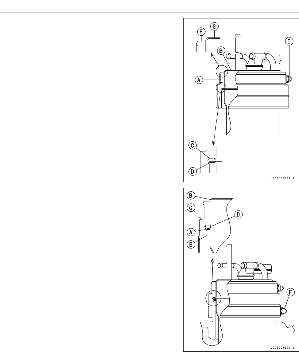
Press down the rubber holder [A] onto the fuel pump [B]
so the stepped part [C] of the holder completely contacts
the flanged part [D] of the pump.
•
Pressing down the rubber holder onto the fuel pump,
tighten the small diameter clamp [E].
NOTE
○
Install the rubber holder onto the fuel pump so the rub-
ber holder top surface [F] must be below the top surface
[G] of the fuel pump to prevent any water from collect-
ing on top of the pump.
•
Install the O-ring [A] to the space between fuel pump [B]
and rubber holder[C] so it completely contacts the flanged
part [D] of the pump.
•
Insert the fuel pump with rubber holder and O-ring into the
tank so its fuel hose fittings face starboard side (see Ca-
ble, Wire, and Hose Routing in Appendix chapter). And
press down the pump so the O-ring [A] completely con-
tacts the top surface of the tank [E].
•
Tighten the large diameter clamp [F] securely.
•
Install the following to the fuel pump.
Fuel Hoses
Fuel Tank Vent Hose
Fuel Pump Lead Connector
○
For JT1500-A2 model; Replace the double spring clamps
with new ones. (see Fuel System Diagram)
NOTE
○
The main fuel hose is larger than the return fuel hose.
Power Source Voltage Inspection
NOTE
○
Be sure t
he battery is fully charged.


