


ELECTRICAL SYSTEM 14-57
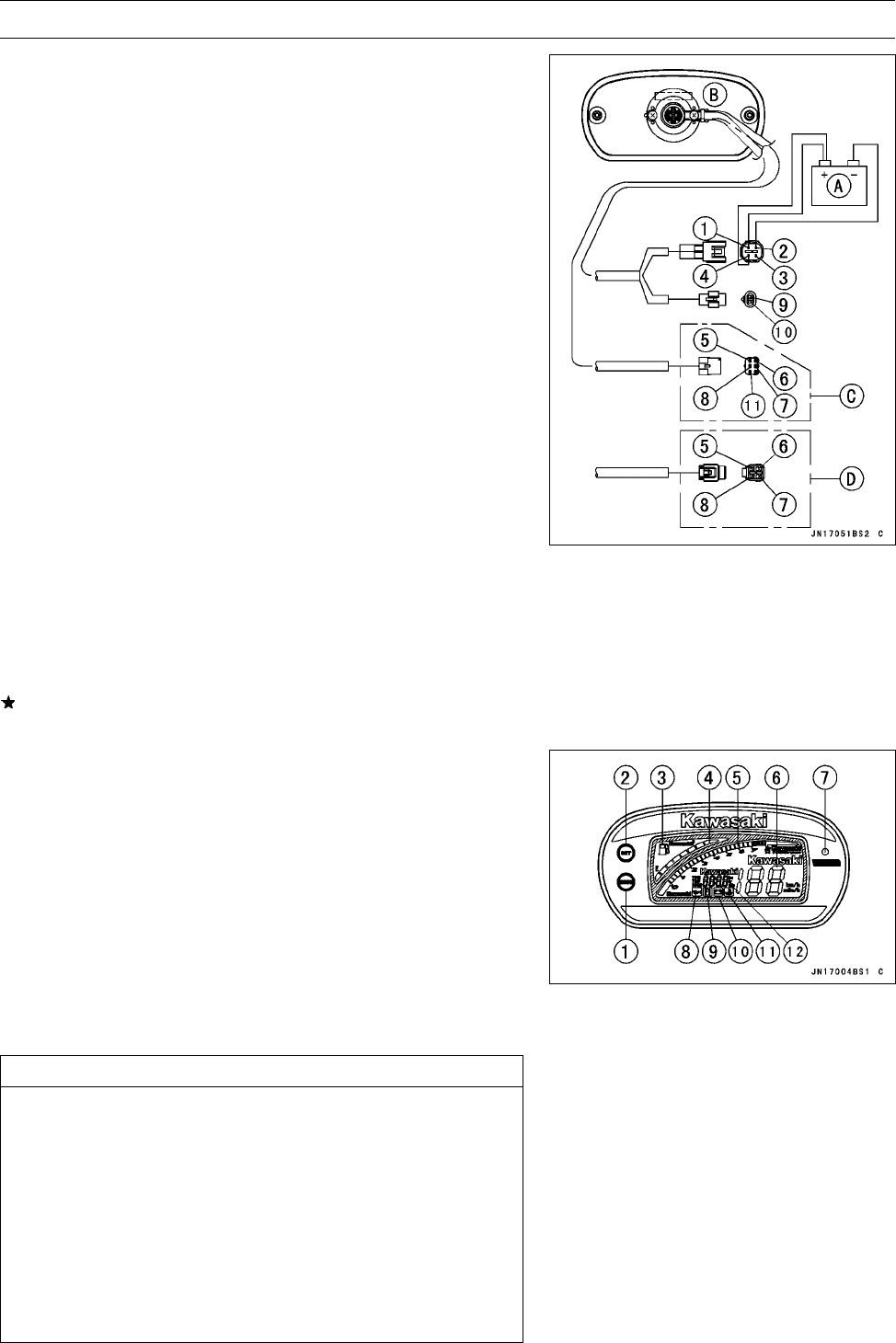
Multifunction Meter
Display Function Inspection
•
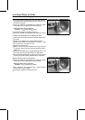
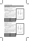
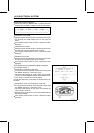
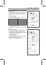
Using the auxiliary wires, connect the 12 V battery [A] to
the meter unit [B] connector as follows.
JT1500-A2 model ∼ [C]
JT1500-A1 model [D]
○
Connect the battery positive terminal to the terminal [1].
○
Connect the battery negative terminal to the terminal [2].
[1] R Battery (+)
[2] BK, Ground (−)
[3] R/BL, Speed Sensor
[4] R/W Ignition Switch (+)
[5] W/R, Fuel Level Sensor
[6] BL/BK, Diagnosis Signal
[7] GY, Tachometer Pulse
[8] G/R, Speed Sensor Pulse
[9] BK/W, Buzzer (−)
[10] R/BK, Buzzer (+)
[11] Y/BL, SLO (Smart Learning Operation) Mode
Battery Voltage Range: 10 ∼ 16 V
•
When the positive terminal (+) of battery is connected
to the terminal [4] completely, inspect that every LCD
segment and LED warning light will be lit for several
seconds just after disappearance of demonstrative fig-
ure-expression.
•
Check that when the terminals are disconnected , all the
LCD segments and LED warning light disappear.
If the LCD segments and LED warning light will not ap-
pear, replace the meter assembly.
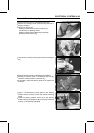
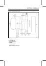
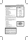
[1] MODE Button
[2] SET Button
[3] Fuel Indicator
[4] Fuel Level Gauge
[5] Tachometer
[6] Speedometer
[7] “LED” Warning Light
[8] Engine Oil Pressure Indicator
[9]FIIndicator
[10] Low Battery Voltage Indicator
[11] Engine Cooling Water Temperature Indicator
[12] Multifunction Display
CAUTION
Do not drop the meter unit. Do not short the termi-
nals.
If the multifunction meter displays incorrectly while
the engine is running, first disconnect the (–) bat-
tery terminal lead and reconnect it again to recover
the meter display.
Then, check to see that the standard plugs and/or
plug caps are installed. Install only the standard
plugs and/or plug caps. The resistors are embed-
ded in both parts.