


APPENDIX 16-9
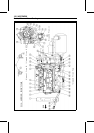
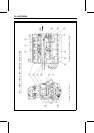
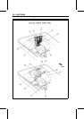
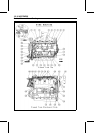
Cable, Wire and Hose Routing
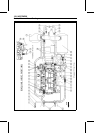
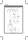
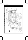
Refer to the Exploded View and Flow Diagram in the Cooling and Bilge Systems chapter.
Install the clamp as shown, noting its screw head direction.
1. Bypass Outlet
2. Clamp
3. Holder
4. Bypass Outlet Hose: Run the bypass outlet hose between the fuel tank and the straps as shown.
5. Cooling Hose (Oil Cooler ∼ Exhaust Manifold): Run the cooling hose between the fuel tank and
the straps as shown.
6. Cooling Hose (Pump ∼ Oil Cooler)
7. Oil Cooler
8. Water Pipe on the Cylinder Head
9. Position the clamp screw head as shown.
10. Cooling Hose (Cylinder Head ∼ Water Pipe Joint under the Left Water Box Muffler)
11. Protective Tube
12. Cooling Hose (Output Cover ∼ Exhaust Pipe)
13. Output Cover
14. Cooling Hose (Pump ∼ Output Cover)
15. Oil Pan
16. Band
17. Right Water Box Muffler
18. Position the clamp so that its screw head faces downward and outside.
19. Position the clamp so that its screw head faces backward.
20. Pump
21. Drain
22. Cooling Hose (Pump ∼ Output Cover)
23. Left Water Box Muffler
24. Cooling Hose (Left Water Box Muffler ∼ Hull)
25. Fix the No.26 and No.27 cooling hoses with the band.
26. Cooling Hose (Output Cover ∼ Exhaust Pipe)
27. Cooling hose (left water box muffler ∼ cylinder): Run the No.27 cooling hose under the No.26
cooling hose as shown.
28. Exhaust Pipe
29. Position the clamp so that its screw head faces inside.
30. Exhaust Manifold
31. Cooling Hose (Oil Cooler ∼ Exhaust Manifold)
32. Fuel Tank
33. Fuel Tank Strap
34. Shift Cable
35. Fix the No. 6 cooling hose and the shift cable with the band.