


3-60 FUEL SYSTEM (DFI)
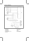
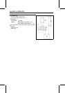
ECU
CAUTION
Never drop the ECU, especially on a hard surface.
Such a shock to the ECU can damage it.
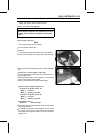
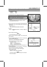
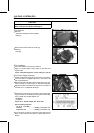
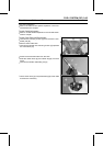
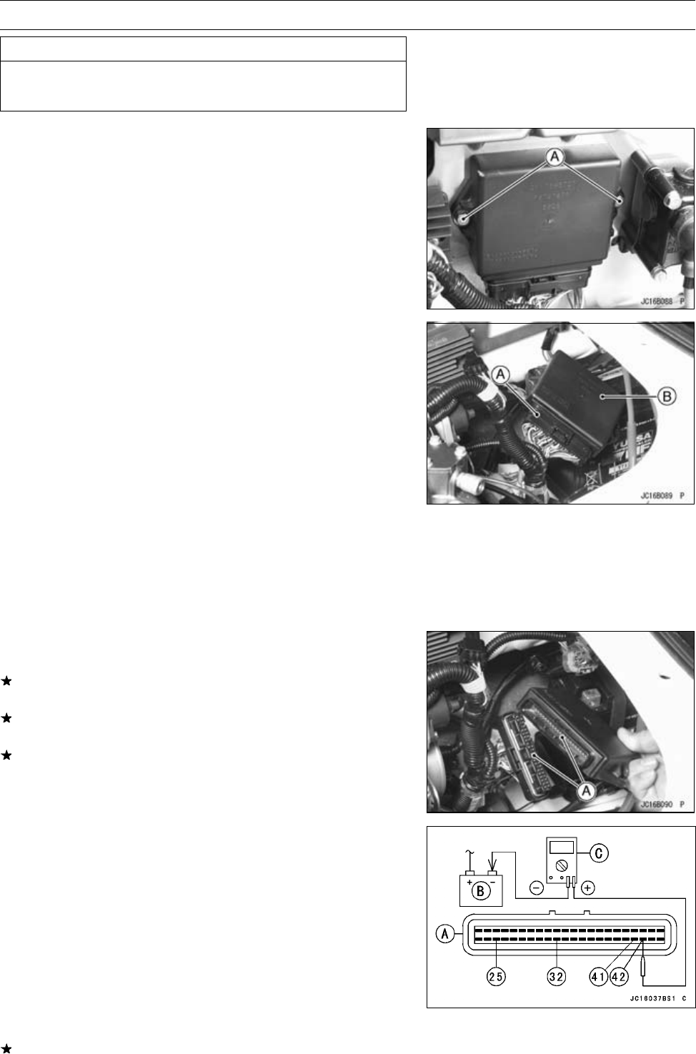
ECU Removal
•
Remove:
Seat (see Hull/Engine Hood chapter)
Bolts [A]
•
Disconnect the ECU lead connector [A].
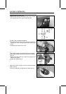
•
Remove:
ECU [B]
ECU Installation
•
Connect the ECU connector and install it.
•
Apply a non-permanent locking agent to the bolts and
tighten them.
Torque - ECU Mounting Bolts: 8.8 N·m (0.90 kgf·m, 78in·lb)
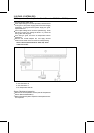
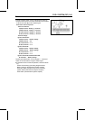
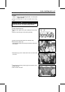
ECU Power Supply Inspection
•
Visually inspect the terminals [A] of the ECU connectors.
If the connector is clogged with mud or dust, blow it off
with compressed air.
Replace the main harness if the terminals of the main har-
ness connector is cracked, bent, or otherwise damaged.
Replace the ECU if the terminals of the ECU connector is
cracked, bent, or otherwise damaged.
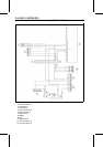
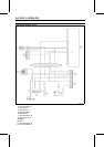
•
With the ECU connector [A] connected, check the follow-
ing ground lead for continuity with the ignition switch OFF,
using a tester and needle adapter set.
[B] Battery
[C] Tester
Special Tool - Needle Adapter Set: 57001-1457
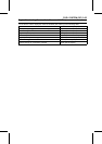
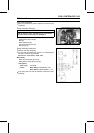
ECU Grounding Inspection
25, 32, 41, or 42 (BK)
Terminal
←→
Battery (–) Terminal: 0 Ω
Engine Ground
←→
Battery (–) Terminal: 0 Ω
If no continuity, check the connector, the engine ground
lead, or main harness, and repair or replace them if nec-
essary.