


ENGINE BOTTOM END 8-21
Crankshaft and Connecting Rods
•
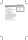
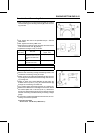
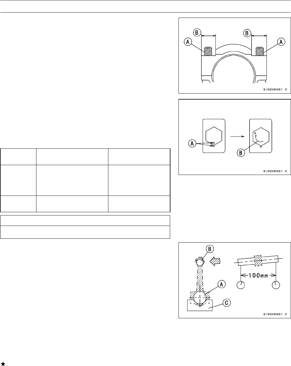
Apply small amount of molybdenum disulfide oil solution
to the threads [A] and seating surfaces [B] of the connect-
ing rod nuts.
•
First, tighten the nuts to the specified torque. See the
table below.
•
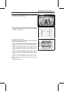
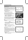
Next, tighten the nuts by 120° more.
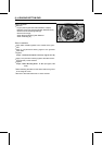
○
Mark [A] the connecting rod big end caps and nuts so that
nuts can be turned 120° [B] properly.
○
Tighten the hexagon nut by 2 corners.
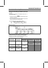
Connecting
Rod Assy
Bolt, Nut
Torque + Angle N·m
(kgf·m, ft·lb)
New Use the bolts and nu ts
attached to new con-rod.
Another new bolts and
nuts.
21.6 (2.2, 16) + 120°
Used Replace the bolts and
nuts with new ones
21.6 (2.2, 16) + 120°
CAUTION
Be careful not to overtighten the nuts.
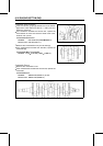
Connecting Rod Bend
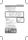
•
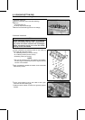
Remove the connecting rod big end bearing inserts, and
reinstall the connecting rod big end caps.
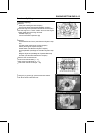
•
Select an arbor [A] of the same diameter as the connect-
ing rod big end, and insert the arbor through the connect-
ing rod big end.
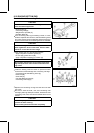
•
Select an arbor of the same diameter as the piston pin
at least 100 mm (3.94 in.) long, and insert the arbor [B]
through the connecting rod small end.
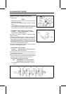
•
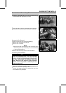
On a surface plate, set the big-end arbor on V blocks [C].
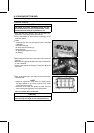
•
Measure the difference in the heights of the arbor above
the surface plate over a 100 mm (3.94 in.) distance-on
the arbor to determine the amount of connecting rod bend
with the connecting rod held vertically, and using a height
gauge.
If connecting rod bend exceeds the service limit, the con-
necting rod must be replaced.
Connecting Rod Bend
Service Limit: 0.2/100 mm (0.008/3.94 in.)