


FUEL SYSTEM (DFI) 3-1
3
Fuel System (DFI)
Table of Contents
Fuel System Diagram........................ 3-3
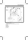
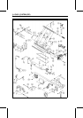
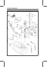
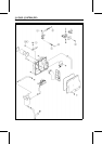
Exploded View................................... 3-4
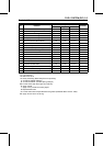
Specifications .................................... 3-10
Special Tools and Sealant ................. 3-12
DFI Parts Location............................. 3-13
DFI System........................................ 3-16
DFI Servicing Precautions................. 3-19
Self-Diagnosis ................................... 3-22
Self-diagnosis Outline..................... 3-22
Service Code (Character) Table ..... 3-23
Troubleshooting the DFI System ....... 3-25
Throttle Sensor (Service
Code/Character-11/tPS) ................. 3-27
Throttle Sensor Removal/Adjust-
ment .......................................... 3-27
Input Voltage Inspection............... 3-28
Output Voltage Inspection............ 3-30
Resistance Inspection.................. 3-31
Inlet Air Pressure Sensor (Service
Code/Character-12/bOSt)............... 3-33
Inlet Air Pressure Sensor
Removal.................................... 3-33
Inlet Air Pressure Sensor
Installation................................. 3-33
Input Voltage Inspection............... 3-33
Output Voltage Inspection............ 3-34
Inlet Air Temperature Sensor (Service
Code/Character-13/AIrt) ................. 3-36
Inlet Air Temperature
Removal/Installation.................. 3-36
Output Voltage Inspection............ 3-36
Sensor Resistance Inspection ..... 3-37
Water Temperature Sensor (Service
Code/Character-14/AqUt)............... 3-39
Water Temperature Sensor
Removal/Installation.................. 3-39
Output Voltage Inspection............ 3-39
Sensor Resistance Inspection ..... 3-41
Crankshaft Sensor (Service
Code/Character-21/CrAg)............... 3-42
Crankshaft Sensor
Removal/Installation.................. 3-42
Crankshaft Sensor Inspection...... 3-42
Camshaft Position Sensor (Service
Code/Character-23/CAAg).............. 3-43
Camshaft Position Sensor
Removal/Installation.................. 3-43
Camshaft Position Sensor
Inspection.................................. 3-43
Vehicle-down Sensor (Service
Code/Character-31/dOS)................ 3-44
Vehicle-down Sensor Removal.... 3-44
Vehicle-down Sensor Installation. 3-44
Vehicle-down Sensor Inspection.. 3-45
Fuel Injectors (Service
Code/Character-41, 42, 43,
44/InJ1, InJ2, InJ3, InJ4) ................ 3-47
Fuel Injector Removal.................. 3-47
Fuel Injector Installation............... 3-47
Audible Inspection........................ 3-48
Injector Signal Test....................... 3-48
Injector Resistance Inspection..... 3-49
Injector Unit Test .......................... 3-49
Injector Voltage Inspection........... 3-50
Injector Fuel Line Inspection........ 3-51
Ignition Coils (Service
Code/Character-51, 52/COL1,
COL2) ............................................. 3-53
Ignition Coil Removal/Installation. 3-53
Input Voltage Inspection............... 3-53
Engine Overheating (Service
Code/Character-71/HEAt)............... 3-55
Low Engine Oil Pressure (Service
Code/Character-72/OILP)............... 3-56
Oil Temperature Sensor (Service
Code/Character-73/OILC or
73/OILt)........................................... 3-57
Oil Temperature Sensor
Removal/Installation.................. 3-57
Output Voltage Inspection............ 3-57
Sensor Resistance Inspection ..... 3-58
Engine Oil Overheating (Service
Code/Character-76/OILH)............... 3-59
ECU................................................... 3-60
ECU Removal .............................. 3-60
ECU Installation ........................... 3-60
ECU Power Supply Inspection..... 3-60
DFI Power Source ............................. 3-63
Main Fuse Inspection................... 3-63
Relay Assembly Removal............ 3-63
Relay Assembly Inspection.......... 3-63