


14-38 ELECTRICAL SYSTEM
Ignition System
•
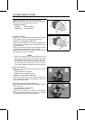
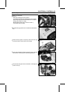
Apply grease to the O-ring and fit it in the groove of the
sensor cover.
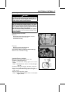
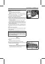
•
Apply silicone sealant [A] to the crankcase halves mating
surface on the right and left sides of the crankshaft sensor
mount.
Sealant - Kawasaki Bond (Silicone Sealant): 56019-120
•
Install the crankshaft s ensor cover.
Torque - Crankshaft Sensor Cover Bolts: 7.8 N ·m (0.80
kgf·m, 69 in·lb)
•
Install the Engine (see Engine Removal/Installation chap-
ter).
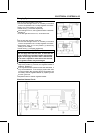
Timing Rotor Removal
•
Remove the engine (see Engine Removal).
•
Remove the crankshaft sensor cover (see Crankshaft
Sensor Removal).
•
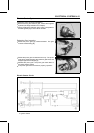
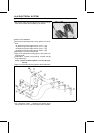
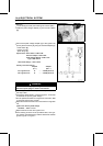
Remove the timing rotor [A].
○
Holding the timing rotor with the flywheel and pulley holder
[B] and unscrew the bolt [C].
Special Tools - Flywheel & Pulley Holder: 57001-1605
Flywheel and Pulley Holder Adapter: 57001
-1547 [D]
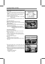
Timing Rotor Installation
•
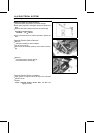
Fit the rotor to the crankshaft.
•
Apply a non-permanent locking agent to the rotor bolt.
•
Tighten the rotor bolt.
Torque - Timing Rotor Bolt: 20 N·m (2.0 kgf·m, 14 ft·lb)
•
Install the crankshaft sensor cover (see Crankshaft Sen-
sor C over Installation).
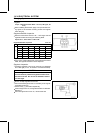
Crankshaft Sensor Inspection
•
Remove:
Seat (see Hull/Engine Hood chapter)
•
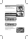
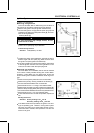
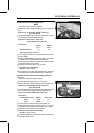
Disconnect the 2-pin crankshaft sensor leads connector
(Blue) [A].
•
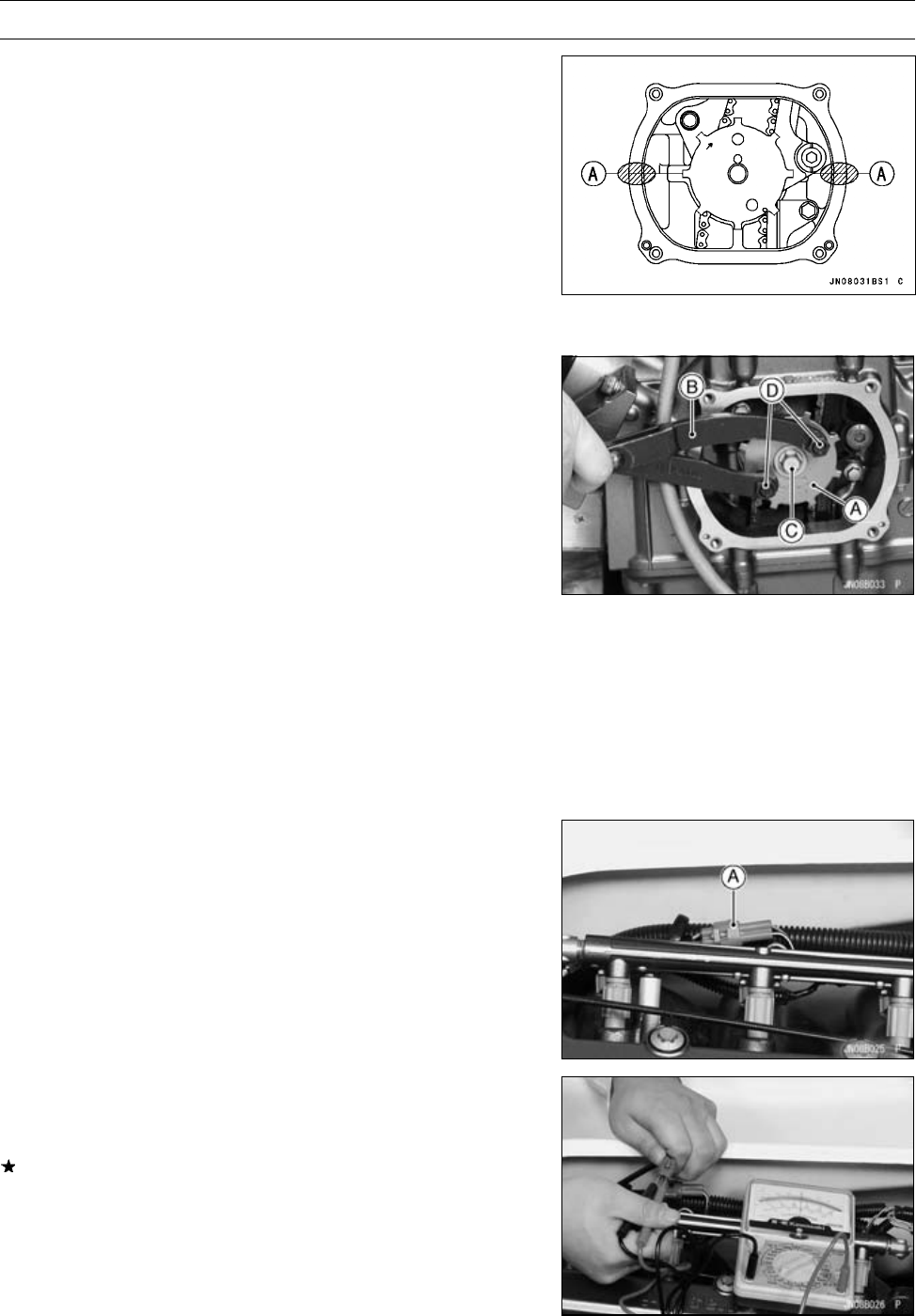
Set the hand tester to the × 100 Ω range, zero it, and
connect it to the crankshaft sensor lead terminals (G and
BL) in the connector.
If there is more resistance than the specified value, the
sensor has an open lead and must be replaced. Much
less than this resistance means the sensor is shorted, and
must be replaced.
Crankshaft Sensor Resistance
Standard: 408 ∼ 612 Ω