ELECTRICAL SYSTEM 14-35
Charging System
•
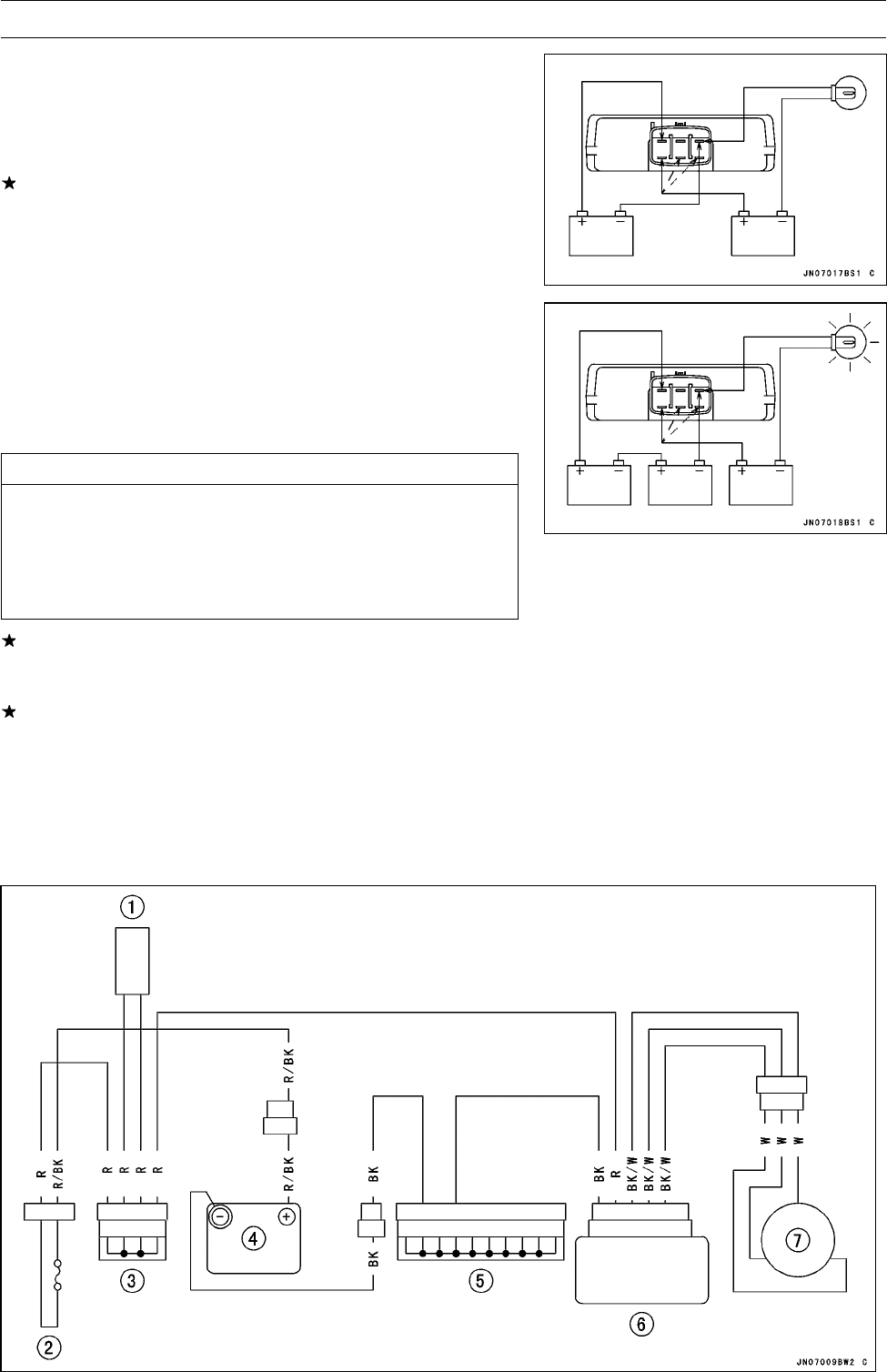
Do the 2nd step regulator circuit test.
○
Connect the test light and the 12 V battery in the same
manner as specified in the “1st step regulator circuit test”.
○
Apply12Vtothepositive(+)terminal.
○
Check infinity (∼) terminals respectively.
If the test light turns on, the regulator/rectifier is defective.
Replace it.
○
If the test light does not turn on, continue the test.
•
Do the 3rd step regulator circuit test.
○
Connect the test light and the 12 V battery in the same
manner as specified in the “1st step regulator circuit test”.
○
Momentarily apply 24 V to the positive (+) terminal by
adding a 12 V battery.
○
Check infinity (∼) terminals respectively.
CAUTION
Do not apply more than 24 volts. If more than 24
volts is applied, the regulator/rectifier may be dam-
aged. Do not apply 24 V more than a few seconds.
If 24 volts is applied for more than a few seconds,
the regulator/rectifier may be damaged.
If the test light does not light when 24 V is applied momen-
tarily to the positive (+) terminal, the regulator/rectifier is
defective. R eplace it.
If the regulator/rectifier passes all the tests described, it
may still be defective. If the charging system still does
not work properly after c hecking all the components and
the battery, test the regulator/rectifier by replacing it with
a known good unit.
•
Repeat the test for another regulator/rectifier.
Charging System Circuit


