3-40 FUEL SYSTEM (DFI)
Water Temperature Sensor (Service Code/Character-14/AqUt)
•
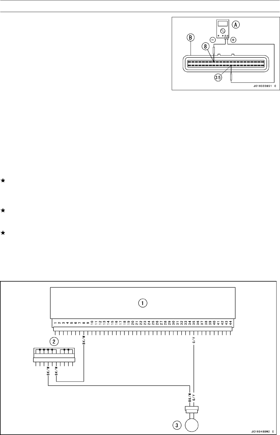
Connect a digital voltmeter [A] to the ECU connector [B],
with the needle adapter set.
Special Tool - Needle Adapter Set: 57001-1457
Water Temperature Sensor Output Voltage
Connections to ECU
Meter (+) → G/Y lead (terminal 35)
Meter (–) → BK/W lead (terminal 8)
•
Turn the ignition switch ON and push the lanyard key un-
der the stop button.
•
Pushing the start button, run the engine 5 ∼ 6 seconds at
idling to measure the sensor output voltage.
○
Wait 15 seconds before using the starter again.
Output Voltage at ECU
Standard: about 3 ∼ 4 V at 20°C (68°F)
NOTE
○
The output voltage changes according to the coolant
temperature in the engine.
•
Turn the ignition switch OFF.
If the output voltage is out of the specified, check the ECU
for its ground, and power supply (see ECU Power S upply
Inspection). If the ground and power supply are good,
replace the ECU.
If the output voltage is far out of the specified (e.g. when
the wiring is open, the voltage is about 5 V), check the
wiring (see next diagram).
If the wiring is good, check the water temperature sensor
resistance.
•
Remove the needle adapter set, and apply silicone
sealant to the seals of the connector for waterproofing.
Silicone Sealant (Kawasaki Bond: 56019-120) -Seals
of ECU Connectors


