


ELECTRICAL SYSTEM 14-43
Ignition System
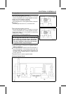
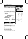
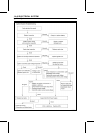
Camshaft Position Sensor Inspection
•
Remove:
Seat (see Hull/Engine Hood chapter)
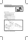
Camshaft Position Sensor Lead Connector [A] (discon-
nect)
•
Set the hand tester [B] to the × 10 Ω range and connect it
to the yellow and black leads in the connector.
Special Tool - Hand Tester: 57001-1394
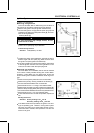
If there is more resistance than the specified value, the
sensor coil has an open lead and must be replaced. Much
less than this resistance means the sensor coil is shorted,
and must be replaced.
Camshaft Position Sensor Resistance: 400 ∼ 460 Ω
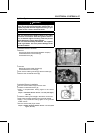
•
Using the highest resistance range of the tester, mea-
sure the resistance between the camshaft position sensor
leads and chassis ground.
Any tester reading less than infinity (∞) indicates a short,
necessitating replacement of the camshaft position sen-
sor.
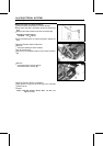
Igniter Removal/Installation
•
Refer to ECU Removal in the Fuel System (DFI) chapter.
Igniter Inspection
○
The igniter is built in the ECU (E
lectronic Control Unit).
CAUTION
Do not disconnect the battery lead
s or any other
electrical connections when the ignition switch is
on, or while the engine is running. This is to prevent
igniter in the ECU damage.
Ignition Coil Primary Peak Voltage Check
NOTE
○
Be sure the battery is fully charged.
•
Remove:
Seat (see Hull/Engine Hood chapter)
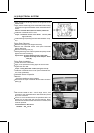
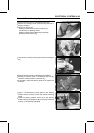
•
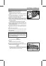
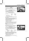
Pull all the spark plug caps from the spark plugs.
•
Install the new spark plugs [A] into each plug caps [B],
and ground them onto the engine.
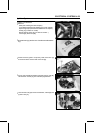
NOTE
○
Maintain the correct value of compression pressure for
the cylinder (Be sure to measure the voltage with the
spark plug installed to the cylinder head).