


FUEL SYSTEM (DFI) 3-37
Inlet Air Temperature Sensor (Service Code/Character-13/AIrt)
If the output voltage is out of the specified, check the ECU
for its ground, and power supply (see ECU Power Supply
Inspection). If the ground and power supply are good,
replace the ECU.
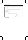
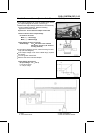
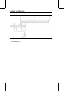
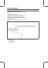
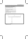
If the output voltage is far out of the specified, check the
wiring (see next diagram).
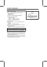
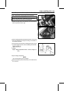
•
Remove the needle adapter set, and apply silicone
sealant to the seals of the connector for waterproofing.
Silicone Sealant (Kawasaki Bond: 56019-120) -Seals
of ECU Connectors
If the wiring is good, check the sensor resistance.
Sensor Resistance Inspection
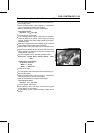
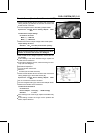
•
Remove the inlet air temperature sensor (see Inlet Air
Temperature Sensor Removal).
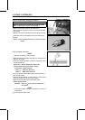
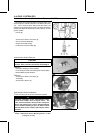
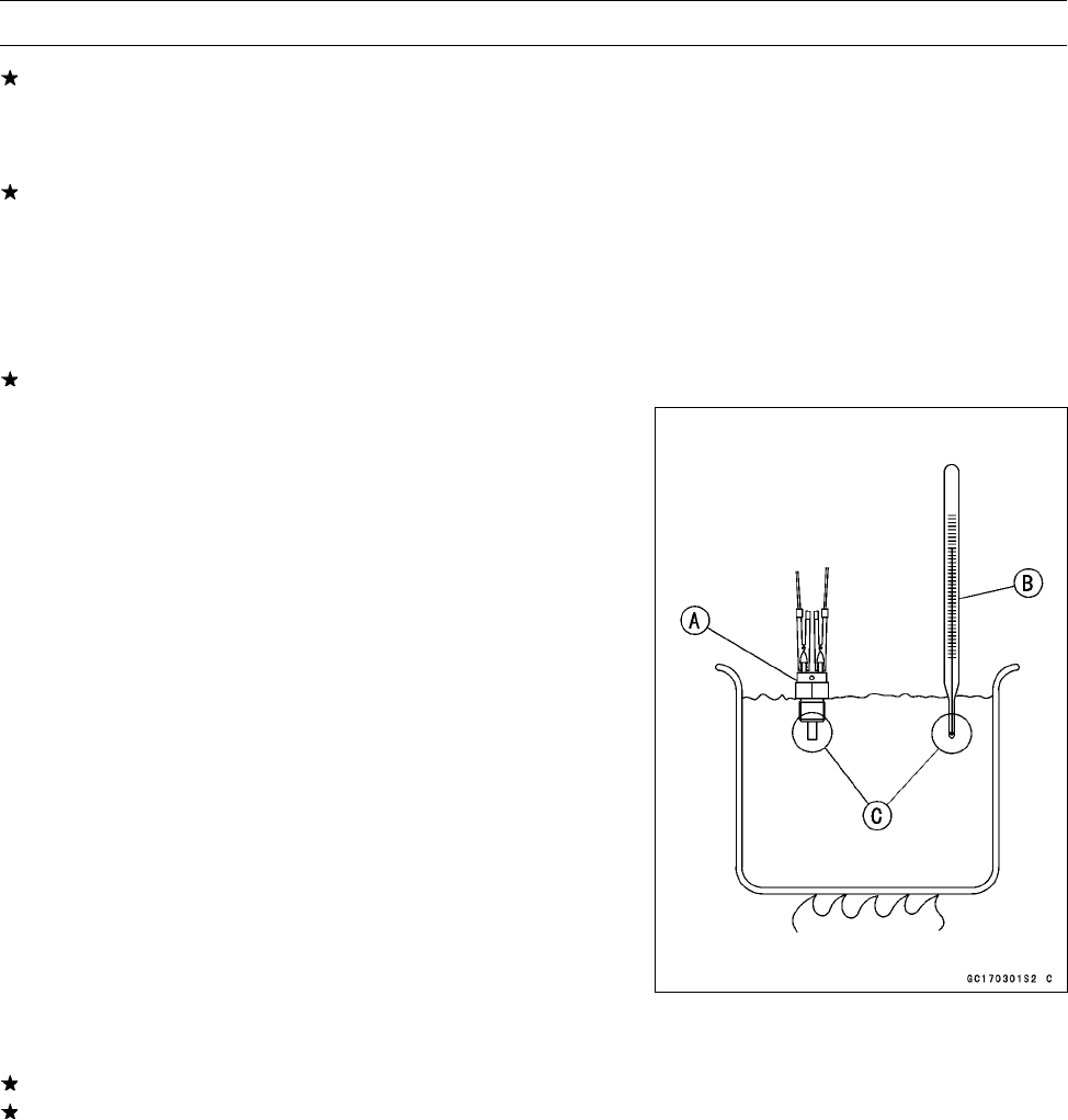
•
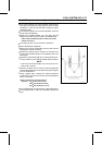
Suspend the sensor [A] in a container of machine oil so
that the heat-sensitive portion and threaded portion are
submerged.
•
Suspend a thermometer [B] with the heat-sensitive por-
tion [C] located in almost the same depth with the sensor.
NOTE
○
The sensor and thermometer must not touch the con-
tainer side or bottom.
•
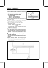
Place the container over a source of heat and gradually
raise the temperature of the oil while stirring the oil gently
for even temperat
ure.
•
Using a digital meter, measure the internal resistance
of the sensor across the terminals at the temperatures
shown in the table.
Inlet Air Temperature Sensor Resistance
Standard: 5.4 ∼ 6.6 kΩ at 0°C (32°F )
2.26 ∼ 2.86 kΩ at 20°C (68°F)
0.29 ∼ 0.39 kΩ at 80°C (176°F)
If the measurement is out of the range, replace the sensor.
If the measurement is within the specified, replace the
ECU.