ELECTRICAL SYSTEM 14-33
Charging System
Magneto Output Voltage
•
Remove:
Seat (see Hull/Engine Hood chapter)
Air Filter with Duct (see Fuel System chapter)
•
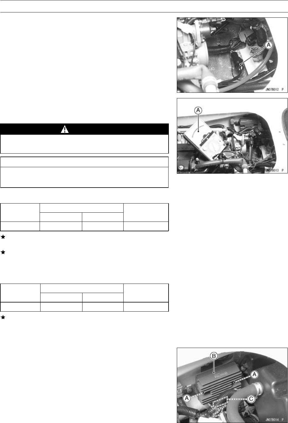
Disconnect the 3-pin stator coil leads connector [A].
•
With the hand tester [A] check the magneto output (in
circuit) according to the following table with the engine
running at approximately 3 000 rpm.
WARNING
To avoid electrical shock, do not perform this test
with the watercraft in the water.
CAUTION
Do not run the engine over 15 seconds without cool-
ing water.
Magneto Output Voltage
Connections
Meter Setting
Meter (+) to Meter (–) to
Standard Value
250 V AC
White lead White lead 48 ∼ 72 V
If the magneto output voltage is correct, check the regu-
lator according to the regulator test procedure.
If the magneto output voltage is low, check the stator coil
resistance with a multimeter according to the following
table.
Stator Coil Resistance Test
Connections
Meter Setting
Meter (+) to Meter (–) to
Standard Value
R×1Ω
White lead White lead
0.432 ∼ 0.648 Ω
If the coil has normal resistance, but the voltage check
shows the charging system to be defective, then the
permanent magnets in the flywheel have probably weak-
ened, necessitation flywheel replacement.
Regulator/Rectifier Removal/Installation
•
Remove the seat (see Hull/Engine Hood chapter).
•
Unscrew the mounting bolts [A] and remove the regula-
tor/rectifier [B].
•
Disconnect the connector [C].


