STEERING 12-15
Steering
•
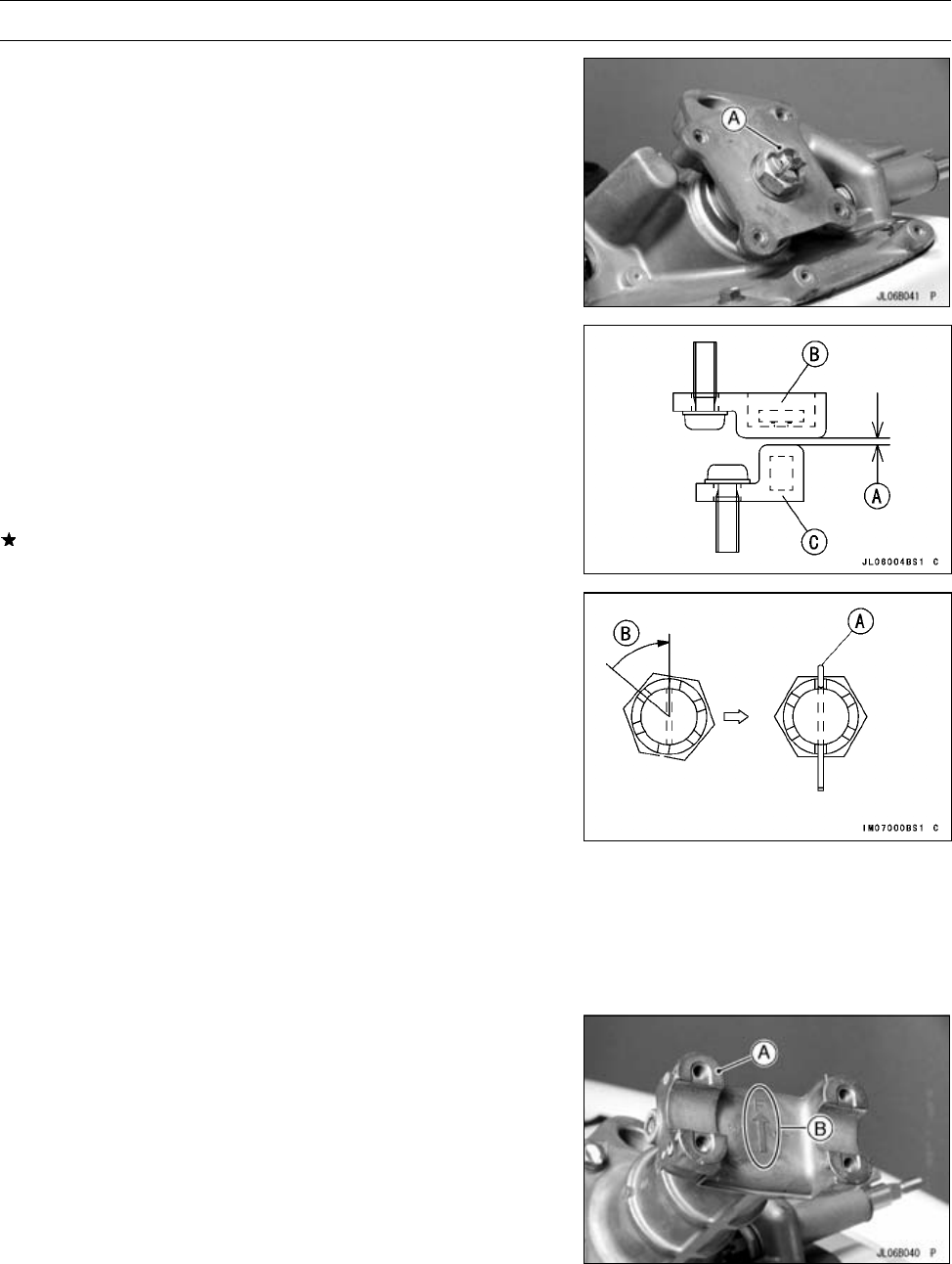
Torque the steering shaft locknut [A].
Torque - Steering Shaft Locknut: 49 ∼ 59 N·m (5.0 ∼ 6.0
kgf·m, 36 ∼ 43 ft·lb)
•
Turning the steering shaft fully in left and right direction,
check whether the steering position sensor comes in con-
tact with the magnet.
•
Check the clearance [A] between the steering position
sensor [B] and the magnet [C] with feeler gauge.
Steering Position Sensor Clearance
Standard: 0.5 ∼ 1.5 mm (0.02 ∼ 0.06 in.)
If necessary, adjust the clearance by turning the steering
shaft nut.
•
Replace the cotter pin [A] with a new one.
NOTE
○
When inserting the cotter pin, if the slots in the locknut
do not align with the cotter pin hole in the steering shaft,
tighten the locknut clockwise [B] up to next alignment.
○
It should be within 30 degree.
○
Loosen once and tighten again when the slot goes past
the nearest hole.
•
Band the cotter pin over the nut.
•
Install the steering holder.
•
Apply a non-permanent locking agent to the steering
holder mounting bolts.
Torque - Steering H older Mounting Bolts: 20 N·m (2.0
kgf·m , 14.5 in·lb)
•
Install the steering neck [A] so that its arrow mark [B]
points toward the front.
•
Apply a non-permanent locking agent to the steering neck
mounting bolts.
Torque - Steering Neck Mounting Bolts: 16 N·m (1.6 kgf·m,
12 ft·lb)


