


3-34 FUEL SYSTEM (DFI)
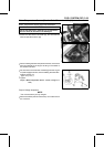
Inlet Air Pressure Sensor (Service Code/Character-12/bOSt)
If the reading is within the standard range, and check the
input voltage at the sensor connector.
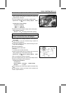
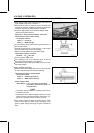
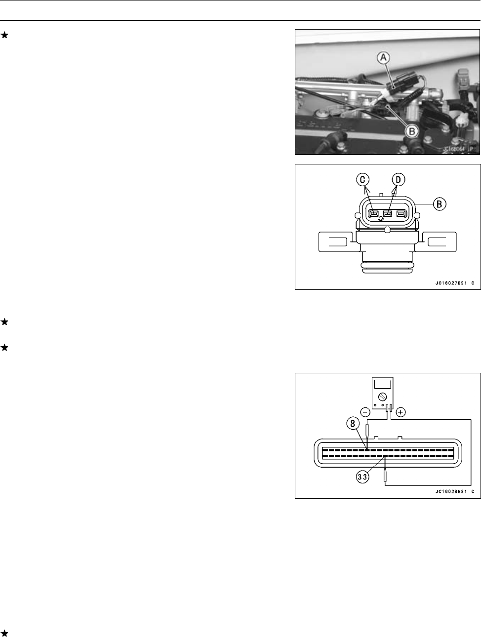
•
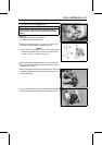
Disconnect the inlet air pressure sensor connector and
connect the harness adapter [A] between the harness
connector and inlet air pressure sensor connector.
•
Connect a digital meter to the harness adapter leads.
[B] Inlet Air Pressure Sensor
Special Tool - Sensor Harness Adapter: 57001-1561
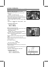
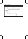
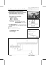
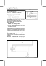
Inlet Air Pressure Sensor Input Voltage
Connections to Sensor
Meter (+) → Rlead[C]
Meter (–) → BK/W lead [D]
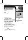
•
Turn the ignition switch ON and push the lanyard key un-
der the stop button.
•
Pushing the start button, run the engine 5 ∼ 6 seconds at
idling to measure the sensor input voltage.
○
Wait 15 seconds before using the starter again.
Input Voltage at Sensor Connector
Standard: 4.75 ∼ 5.25 V DC
•
Turn the ignition switch OFF.
If the reading is out of the standard range, check the
wiring (see Wiring Diagram in this section).
If the reading is good, the input voltage is normal. Check
the output voltage.
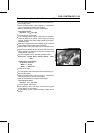
Output Voltage Inspection
•
Measure the output voltage at the ECU in the same way
as input voltage inspection. Note the following.
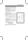
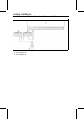
Inlet Air Pressure Sensor Output Voltage
Connections to ECU
Meter (+) → G/R lead (terminal 33)
Meter (–) → BK/W lead (terminal 8)
Output Voltage at ECU
Usable Range:
3.75 ∼ 4.25 V DC at the standard
atmospheric pressure (101.32 kPa, 76
cmHg absolute)
NOTE
○
The output voltage changes according to the local at-
mospheric pressure.
○
The vacuum sensor output voltage is based on a nearly
perfect vacuum in the small chamber of the sensor. So,
the sensor indicates absolute v acuum pressure.
If the output voltage is within the usable range, check
the ECU for its ground, power supply and wiring. If the
ground, power supply and wiring are good, replace the
ECU.