


190-01255-00 Rev. B
Garmin G1000H
™
Pilot’s Guide for the Bell 407GX
11
SYSTEM OVERVIEW
1.5 SYSTEM POWER-UP
NOTE: Refer to the Appendices for AHRS initialization bank angle limitations.
NOTE: See the Appendices for additional information regarding system-specific annunciations and alerts.
NOTE: See the Rotorcraft Flight Manual Supplement (RFMS) for specific procedures concerning avionics
power application and emergency power supply operation.
The G1000H system is integrated with the aircraft electrical system and receives power directly from electrical
busses. The G1000H PFD, MFD and supporting sub-systems include both power-on and continuous built-in test
features that exercise the processor, RAM, ROM, external inputs and outputs to provide safe operation.
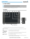
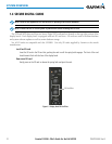
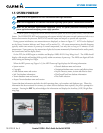
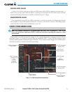
During system initialization, test annunciations are displayed, as shown in Figure 1-7. ALTN is also displayed
on the Power Situation Indicator and Torque will be marked Q
A
. All system annunciations should disappear
typically within one minute of power-up at nomal temperature, but may take as long as 10 minutes at cold
temperatures. Upon power-up, key annunciator lights also become momentarily illuminated on the audio panels,
the control units and the display bezels.
On the PFD, the AHRS begins to initialize and displays ‘AHRS ALIGN: Keep Wings Level’. The AHRS should
display valid attitude and heading fields typically within one minute of power-up. The AHRS can align itself both
while taxiing and during level flight.
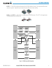
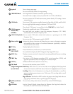
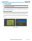
When the MFD powers up (Figure 1-6), the MFD Power-up Page displays the following information:
•Systemversion
•Copyright
•Landdatabasenameandversion
•SafeTaxidatabaseinformation
•Terraindatabasenameandversion
•AirportTerraindatabasenameandversion
•Obstacledatabasenameandversion
• Navigationdatabasename,version,andeffectivedates
•AirportDirectoryname,versionandeffectivedates
•FliteCharts/ChartViewdatabaseinformation
•PilotProleselection
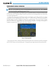
Current database information includes the valid operating dates, cycle number and database type. When this
information has been reviewed for currency (to ensure that no databases have expired), the pilot is prompted to
continue. Pressing the
ENT
Key
acknowledges this information and displays the Auxiliary (AUX) Weight Plan-
ning Page.
Figure 1-6 MFD Power-up Page
Figure 1-7 PFD Initialization