


190-01255-00 Rev. B
Garmin G1000H
™
Pilot’s Guide for the Bell 407GX
59
FLIGHT INSTRUMENTS
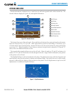
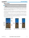
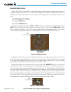
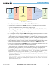
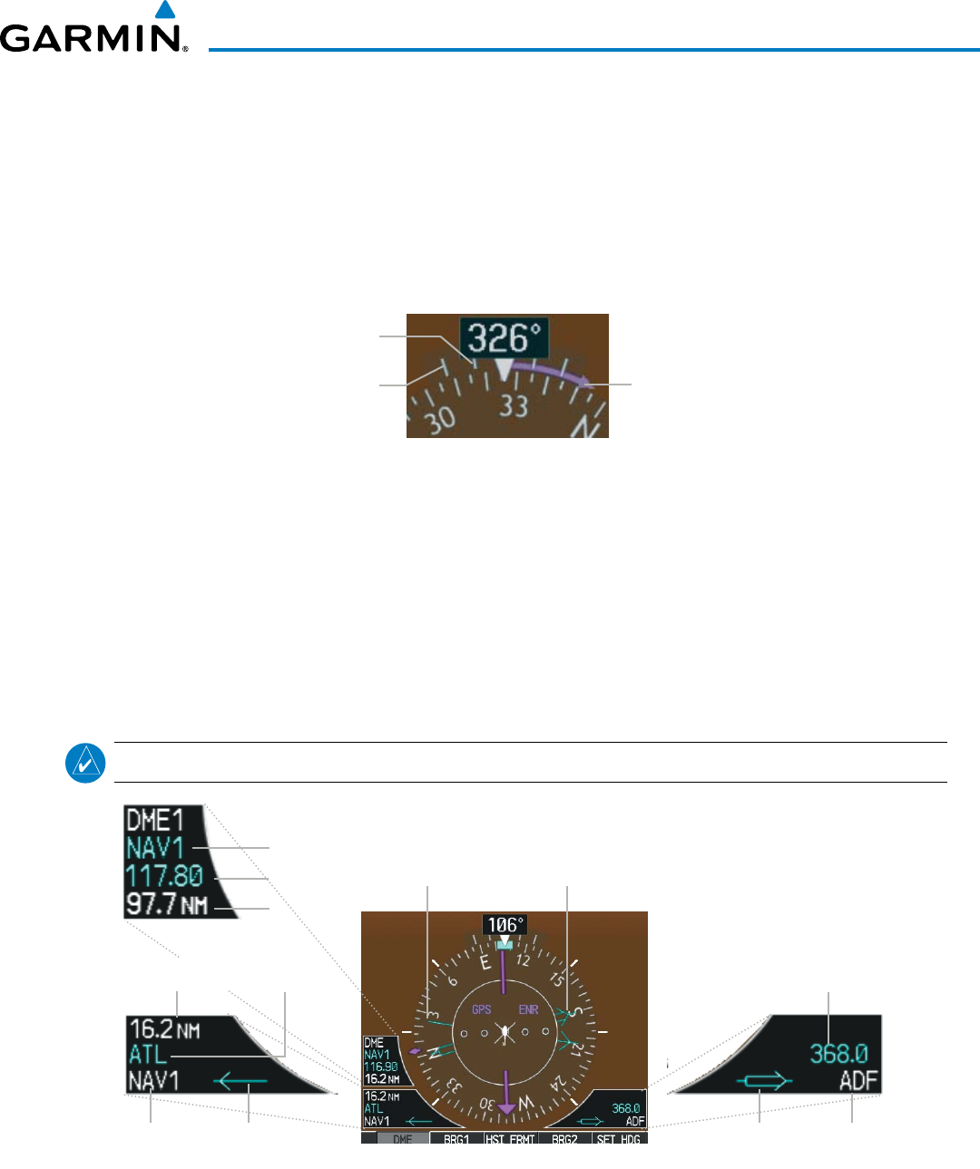
TURN RATE INDICATOR
The TurnRateIndicatorislocateddirectlyabovetherotatingcompasscard.Tickmarkstotheleftandright
ofthelubberlinedenotehalf-standardandstandardturnrates.AmagentaTurnRateTrendVectorshowsthe
currentturnrate.Theendofthetrendvectorgivestheheadingpredictedin6seconds,basedonthepresent
turnrate.Astandard-rateturnisshownontheindicatorbythetrendvectorstoppingatthestandardturn
ratetickmark,correspondingtoapredictedheadingof18˚fromthecurrentheading.Atratesgreaterthan4
deg/sec,anarrowheadappearsattheendofthemagentatrendvectorandthepredictionisnolongervalid.
Arrow Shown
for Turn Rate
> 4 deg/sec
Half-standard
Turn Rate
Standard
Turn Rate
Figure 2-21 Turn Rate Indicator and Trend Vector
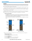
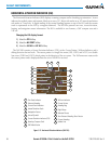
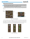
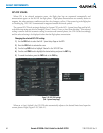
BEARING POINTERS AND INFORMATION WINDOWS
Two bearingpointers andassociated informationcan bedisplayed onthe HSIfor NAV,GPS, andADF
sources by pressing the PFDSoftkeythenaBRG or DME Softkey.Thebearing pointers are light blue and are
single-line(BRG1)ordouble-line(BRG2).Apointersymbolisshownintheinformationwindowstoindicate
the navigation source. The bearing pointers never override the CDI and are visually separated from the CDI
byawhitering.Bearingpointersmaybeselectedbutnotnecessarilyvisibleduetodataunavailability.When
theArcHSIisdisplayed,theBearingInformationwindowsandpointersaredisabled.
NOTE: ADF radio installation is optional.
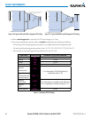
Figure 2-22 HSI with Bearing and Distance Information
Bearing 1
Pointer
Bearing 2
Pointer
Bearing 2 Information Window
ADF
Frequency
Pointer 2
Bearing Source
Bearing 1 Information Window
Bearing Source Pointer 1
Distance to
Bearing Source
Station
Identifier
Frequency
Tuning Mode
Distance